
In embedded system development, serial communication is a fundamental and critical technology. The TMS320F28335, as a widely used MCU, has powerful and flexible serial port functions. This article will delve into the serial port application technology of the 28335, including hardware resources, registers and their settings, application programming methods, and verification through experiments.
1. Hardware Resources of 28335 Serial Port
The TMS320F28335 integrates multiple serial communication modules, commonly referred to as SCI (Serial Communication Interface) modules. These modules provide convenient serial communication channels between the chip and external devices for data transmission and interaction.
(1) Overview of SCI Modules
The 28335 typically has multiple SCI modules, such as SCIA, SCIB, etc. Each SCI module has independent transmitters and receivers, enabling full-duplex or half-duplex communication. This feature allows the 28335 to communicate simultaneously with multiple serial devices, greatly expanding its application scenarios. For example, in industrial automation, different SCI modules can communicate with sensors, actuators, and other devices to achieve comprehensive system control.
(2) Pin Configuration
Each SCI module has corresponding pins. Taking SCIA as an example, its main pins include:
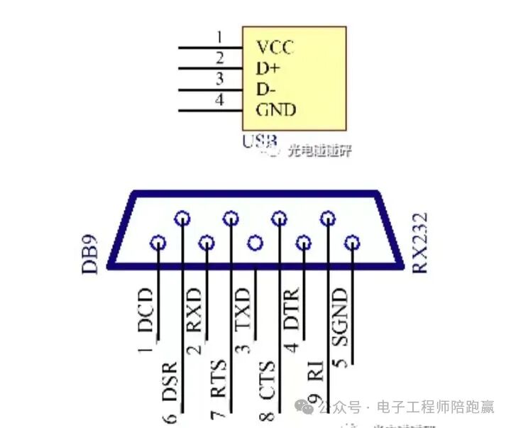
SCITXDA (Transmit Data Pin) and SCIRXDA (Receive Data Pin). Before using the serial port function, the corresponding GPIO pins need to be configured as serial port function pins. This process is completed by setting the GPIO control registers to ensure that the pins can correctly send and receive data.
For example, by setting the corresponding bits of the GpioCtrlRegs.GPBMUX1 register, GPIO35 can be configured as the SCITXDA function, and GPIO36 can be configured as the SCIRXDA function.
2. Registers and Their Settings
The serial communication function of the 28335 is implemented through the configuration of a series of registers, which control various operational parameters and states of the serial port.
(1) Control Registers (SCICTL1, SCICTL2)
1. SCICTL1: Used for basic serial port function control, including software reset (SWRESET), receive enable (RXENA), transmit enable (TXENA), etc. When initializing the serial port, the SWRESET bit is usually cleared first to reset the serial port, and then the RXENA and TXENA bits are set as needed to enable receiving and transmitting functions. For example:
SciaRegs.SCICTL1.bit.SWRESET = 0; // Reset SCI
// Configure other parameters
SciaRegs.SCICTL1.bit.RXENA = 1; // Enable receiving
SciaRegs.SCICTL1.bit.TXENA = 1; // Enable transmitting
SciaRegs.SCICTL1.bit.SWRESET = 1; // Exit reset state
2. SCICTL2: Mainly used for interrupt-related control, such as transmit interrupt enable (TXINTENA), receive interrupt enable (RXBKINTENA), etc.
When using serial port interrupts for data transmission and reception, the corresponding interrupt enable bits need to be set. For example, to enable the receive interrupt:
SciaRegs.SCICTL2.bit.RXBKINTENA= 1; // Enable receive interrupt
(2) Baud Rate Setting Registers (SCIHBAUD, SCILBAUD)
The 28335 sets the baud rate through the SCIHBAUD and SCILBAUD registers.
The calculation formula is:
BRR = LSPCLK / (Baud * 8) – 1, where LSPCLK is the low-speed peripheral clock frequency, and Baud is the desired baud rate.
For example, if LSPCLK is 37.5MHz and the desired baud rate is 9600, the calculated BRR value is:
uint16_t BRR;
BRR = 37500000 / (9600 * 8) – 1;
SciaRegs.SCIHBAUD = BRR >> 8; // Set high 8 bits
SciaRegs.SCILBAUD = BRR & 0x00FF; // Set low 8 bits
(3) Data Format Register (SCICCR)
SCICCR register is used to set the data format of the serial port, including data bit length (SCICHAR), parity bit (PARITYENA), stop bit length (STOPBITS), etc.
The common setting is 8 data bits, no parity bit, and 1 stop bit, configured as follows:
SciaRegs.SCICCR.bit.SCICHAR = 7; // 8 data bits
SciaRegs.SCICCR.bit.PARITYENA = 0; // No parity
SciaRegs.SCICCR.bit.STOPBITS = 0; // 1 stop bit
(4) FIFO Control Registers (SCIFFTX, SCIFFRX, SCIFFCT)
1. SCIFFTX: Used to control the transmit FIFO (First-In-First-Out) queue, including enabling FIFO (SCIFFTX.bit.TXFIFOENA), setting transmit interrupt level (SCIFFTX.bit.TXFFIL), etc. For example, to enable the transmit FIFO and set the transmit interrupt level to 4:
SciaRegs.SCIFFTX.bit.TXFIFOENA = 1; // Enable transmit FIFO
SciaRegs.SCIFFTX.bit.TXFFIL = 4; // Set transmit interrupt level to 4
2. SCIFFRX:
Used to control the receive FIFO queue, including enabling FIFO (SCIFFRX.bit.RXFIFOENA), setting receive interrupt level (SCIFFRX.bit.RXFFIL), etc. For example, to enable the receive FIFO and set the receive interrupt level to 4:
SciaRegs.SCIFFRX.bit.RXFIFOENA = 1; // Enable receive FIFO
SciaRegs.SCIFFRX.bit.RXFFIL = 4; // Set receive interrupt level to 4
3. SCIFFCT: Mainly used to control some characteristics of the FIFO, such as the delay of the transmit FIFO. Generally, the default settings can be maintained, that is:
SciaRegs.SCIFFCT.all = 0x0; // Default settings
3. Application Programming Methods
After understanding the hardware resources and configuring the registers, an application program can be written to implement the serial communication function.
(1) Initialization Function
First, an initialization function for the serial port needs to be written to configure the registers mentioned above to put the serial port in a normal working state. Taking SCIA as an example, the initialization function is as follows:
void InitSciA(void)
{
// Enable SCIA peripheral clock SysCtrlRegs.PCLKCR0.bit.SCIAENCLK = 1;
// Initialize SCIA corresponding GPIO
GpioCtrlRegs.GPBPUD.bit.GPIO36 = 0; // Enable pull-up for GPIO36 (SCIRXDA)
GpioCtrlRegs.GPBPUD.bit.GPIO35 = 0; // Enable pull-up for GPIO35 (SCITXDA)
GpioCtrlRegs.GPBQSEL1.bit.GPIO36 = 3; // Set GPIO36 as asynchronous input (SCIRXDA)
GpioCtrlRegs.GPBMUX1.bit.GPIO36 = 1; // Configure GPIO36 as SCIRXDA function
GpioCtrlRegs.GPBMUX1.bit.GPIO35 = 1; // Configure GPIO35 as SCITXDA function
// Reset SCI
SciaRegs.SCICTL1.bit.SWRESET = 0;
// Configure data format
SciaRegs.SCICCR.bit.SCICHAR = 7; // 8 data bits
SciaRegs.SCICCR.bit.PARITYENA = 0; // No parity
SciaRegs.SCICCR.bit.STOPBITS = 0; // 1 stop bit
// Calculate and set baud rate
uint16_t BRR;
BRR = 37500000 / (9600 * 8) – 1;
SciaRegs.SCIHBAUD = BRR >> 8;
SciaRegs.SCILBAUD = BRR & 0x00FF;
// Enable receiving and transmitting
SciaRegs.SCICTL1.bit.RXENA = 1;
SciaRegs.SCICTL1.bit.TXENA = 1;
// Enable FIFO
SciaRegs.SCIFFTX.bit.TXFIFOENA = 1;
SciaRegs.SCIFFRX.bit.RXFIFOENA = 1;
// Set FIFO interrupt level
SciaRegs.SCIFFTX.bit.TXFFIL = 4;
SciaRegs.SCIFFRX.bit.RXFFIL = 4;
// Exit reset state
SciaRegs.SCICTL1.bit.SWRESET = 1;
}
(2) Data Sending Function
A data sending function can be written to send data through the serial port. Sending can be done using polling or interrupt methods. Below is an example of a sending function using polling:
void SciASendChar(char ch)
{
while (SciaRegs.SCIFFTX.bit.TXFFST == 16); // Wait for an empty position in the transmit FIFO
SciaRegs.SCITXBUF = ch; // Write data to the transmit buffer register
}
void SciASendString(char *str)
{
while (*str)
{
SciASendChar(*str++);
}
}
(3) Data Receiving Function
Similarly, a data receiving function can be written using polling or interrupt methods. For example, using interrupts, the interrupt-related registers need to be configured first, and an interrupt service function needs to be written:
// Receive interrupt service function
interrupt void SciaRxFifoIsr(void)
{
char receivedChar;
while (SciaRegs.SCIFFRX.bit.RXFFST > 0) // Check if there is data in the receive FIFO
{
receivedChar = SciaRegs.SCIRXBUF.all & 0xFF; // Read received data
// Process the received data, e.g., store it in a buffer, etc.
}
SciaRegs.SCIFFRX.bit.RXFFINTCLR = 1; // Clear receive interrupt flag
PieCtrlRegs.PIEACK.all=PIEACK_GROUP9; // Acknowledge PIE interrupt
}
// Configure receive interrupt
void ConfigureSciARxInterrupt(void)
{
EALLOW;
PieCtrlRegs.PIEIER9.bit.INTx1 = 1; // Enable PIE group 9 interrupt 1 (SCIA receive interrupt)
IER |= M_INT9; // Enable CPU interrupt 9
EDIS;
}
4. Experiments
To verify the correctness of the above serial port application technology, the following experiments are conducted.
(1) Hardware Connection
Connect the SCIA serial port of the 28335 development board to the PC where the serial debugging assistant is located via a serial cable, ensuring that TX and RX are cross-connected.
(2) Software Implementation
Create a project in the CCS (Code Composer Studio) development environment, and write the above initialization function, data sending function, data receiving function, etc.
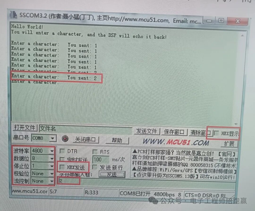
 First, initialize the system clock, PIE interrupt registers, interrupt vector table, and then initialize the hardware port clocks and IO ports used. Then call the SCI initialization function, set the baud rate to 4800, and call the sending function to send two prompt messages. Finally, enter a while loop, waiting for the reception status to complete, receive the following data, and send it to the PC serial port. The time0 indicator light blinks every 200ms, indicating that the system is running normally. Then enter a while loop, waiting for the reception status to complete, receive the following data, and send it to the PC serial port. The time0 indicator light blinks every 200ms, indicating that the system is running normally.In the receive interrupt service function, the received data is processed (here simply printed to the console).
(3) Test Results
Download the program to the 28335 development board, open the serial debugging assistant, set the baud rate (consistent with the settings in the program, such as 9600), data bits, stop bits, parity bits, and other parameters. Observe the serial debugging assistant, and it should be able to receive the string “Hello, 28335 SCI!” sent by the development board. At the same time, when sending data from the serial debugging assistant, it should also be received correctly.
 Previous Recommendations:Building an Efficient and Stable Motor Control DSP Software Framework:Comprehensive Analysis of TMS320F28335’s Three-Level Interrupt Settings and InitializationBasic Experiments on ePWM Configuration of TMS320F28335Most Common 28335 ePWM Configuration Methods for Motor ControlThe Global Craze for the Legendary Chip! How TI C2000 Rewrites Embedded Control History?Unveiling the Bridge Between Analog and Discrete PID Control: Difference EquationsIntelligent Self-Tuning Methods for PID ParametersTrend Curve for Complete Tuning of PID ParametersKey Components of Robots (6) – Stepper MotorsKey Components of Robots (4) – DC Torque MotorsField Effect Transistor Series (9) – Continuation and Drive of H-Bridge Circuits