The position estimation methods for brushless DC motors without position sensors can be discussed from five aspects: back electromotive force method, current method, state observer method, artificial intelligence method, and magnetic flux method. These methods are relatively mature in research and have been applied to a certain extent. The CW32 ecological community frequently uses the back electromotive force method in applications related to square wave control and demos, thus focusing on the back electromotive force rotor position detection technology.
1. Back Electromotive Force Method
In brushless DC motors, the rotor continuously rotates in a certain direction under the influence of the synthetic magnetic field generated by the stator windings. The armature winding is placed on the motor stator, so when the rotor rotates, it cuts the magnetic field lines in space, and according to the law of electromagnetic induction, an induced electromotive force is generated in the conductor. Therefore, when the rotor rotates, an induced electromotive force, known as back electromotive force or back voltage, is generated in the stator windings.
For rare earth permanent magnet brushless DC motors, the air gap magnetic field waveform can be square wave, trapezoidal wave, or sinusoidal wave, which is related to the shape of the permanent magnet, the magnetic circuit structure of the motor, and the magnetization of the magnetic steel. Thus, brushless DC motors can be classified into square wave motors and sinusoidal wave motors. For radial magnetization structures, the rare earth permanent magnet faces the uniform air gap directly, and due to the good orientation of the rare earth permanent magnet, a good square waveform air gap magnetic field can be easily obtained. For motors with square wave air gap magnetic fields, when the stator winding uses concentrated winding, that is, the number of slots per phase per pole is q = 1, the induced electromotive force in the stator winding due to the square wave magnetic field is trapezoidal, as shown in Figure 1.
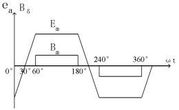
Figure 1 Square wave air gap magnetic field and trapezoidal wave back electromotive force
For two-phase conducting star-connected and three-phase six-state controlled brushless DC motors, the width of the square wave air gap magnetic flux density in space should be greater than 120° electrical degrees, and the flat top width of the trapezoidal wave back electromotive force induced in the stator winding should also be greater than 120° electrical degrees. Square wave brushless DC motors generally use square wave current drive, which matches with the 120° conducting inverter, providing three-phase symmetrical square wave current with a width of 120° electrical degrees to the square wave motor. The square wave current should be in phase with the back electromotive force or within the flat top width range of the trapezoidal wave back electromotive force to satisfy the “optimal commutation logic”.[10].
When the back electromotive force of a certain phase winding of the BLDCM crosses zero, the rotor’s direct axis coincides with the axis of that phase winding. Therefore, by detecting the zero-crossing points of the back electromotive force of each phase winding, several key positions of the rotor can be obtained. After processing these key rotor position signals, the commutation of the BLDCM can be controlled to achieve continuous operation of the BLDCM, which is the “back electromotive force method” for controlling the BLDCM.
From Figure 1, it can be seen that at wt=30° electrical degrees, the moment when the back electromotive force of phase A crosses zero is detected by the control circuit, which delays 30° electrical degrees and switches to phase A conduction at 60° electrical degrees. After 120° electrical degrees of phase A conduction, it turns off phase A at 180° electrical degrees and switches to phase B conduction. By repeating this process, continuous operation of the motor can be achieved while satisfying the “optimal commutation logic”.
The zero-crossing points of the back electromotive force of the brushless DC motor windings strictly reflect the rotor magnetic pole position. Therefore, as long as the zero-crossing signal of the winding back electromotive force can be accurately detected, the key positions of the rotor can be determined. After a 30° electrical degree delay processing, it can be used as the commutation moment of the winding. Then, according to the conduction sequence of the power transistors, the corresponding power transistors can be triggered to achieve the commutation operation of the brushless DC motor, ensuring that the motor rotates continuously in a fixed direction. This ensures that the commutation of the motor meets the “optimal commutation logic” and reduces torque ripple. The specific implementation method for the operation of the sensorless back electromotive force motor can be found in the community open-source cases.
To determine the relationship between motor speed and back electromotive force magnitude, and to provide a theoretical basis for the “three-stage” starting technology of sensorless motors, we derive the calculation formula for the back electromotive force of the BLDCM and analyze the back electromotive force characteristics of brushless DC motors.
For ease of analysis, the transitional process of the switching devices and the inductance of the armature winding are ignored in the formula derivation process. The induced electromotive force of a single conductor in the air gap magnetic field is:
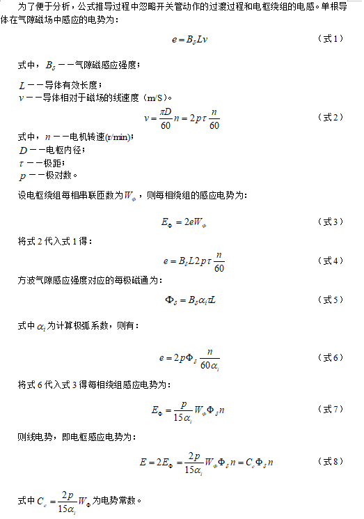
The back electromotive force calculation formula for brushless DC motors is the same as that for general DC motors. The magnitude of the back electromotive force is related to the magnetic flux per pole and the speed. If the magnetic flux per pole is kept constant, the back electromotive force of the brushless DC motor is proportional to the speed; conversely, if the speed is kept constant, the back electromotive force of the brushless DC motor is proportional to the magnetic flux per pole. From formula (8), it can also be seen that when the motor is stationary or at very low speeds, the back electromotive force is zero or very small, making it impossible to obtain rotor position signals from the winding back electromotive force, and the motor cannot self-start. Therefore, the “back electromotive force method” for controlling brushless DC motors must use other methods to start the motor, which will be detailed in later chapters.
2. Other Detection Methods
Current Method
The direct back electromotive force method is implemented by measuring the terminal voltages of the three-phase windings and the voltages between them and the neutral point. When the terminal voltage of a certain phase equals the neutral point voltage, it is considered that the back electromotive force of that phase crosses zero, and then the power switching device is triggered to reverse after a delay of 30 electrical degrees.
Due to the interference from speed variations, motor commutation, low-pass filtering, and the stator resistance and inductance, the accuracy and precision of estimating rotor position signals based on terminal voltage measurements are affected to varying degrees. In contrast, these factors have relatively little impact on the current. Consequently, methods have emerged that estimate rotor position information based on the phase current signals of the motor, thereby controlling the commutation of the brushless DC motor, such as direct current detection method, current rate of change detection method, and freewheeling diode method. The accuracy of this control method is limited by the processor speed and the switching frequency of the power transistors, which can easily lead to the current and back electromotive force operating out of phase, resulting in motor failure.
State Observer Method
The method of estimating rotor position and rotor speed using a Kalman filter was first proposed by M. Schroedl in 1988. According to the Kalman state equations, the rotor position can be initially estimated using the measured voltage and current of the motor. The operational range of this method for predicting rotor position and rotor speed is mainly determined by the measurement accuracy of the voltage and current sensors.
Artificial Intelligence Method
Artificial intelligence technology possesses certain intelligent behaviors and can generate appropriate responses to problem-solving. With the rapid development and in-depth research of artificial intelligence technology, many scholars have attempted to apply artificial intelligence methods to motor control. Neural networks are one direction of artificial intelligence control, characterized by strong adaptability and self-learning capabilities. Therefore, introducing neural network technology into brushless DC motor control for speed estimation and position estimation is a natural step. When predicting rotor position using this method, the operational range is mainly influenced by the detection accuracy of voltage and current.
Magnetic Flux Method
By establishing a magnetic flux function that does not depend on rotor speed but is directly related to rotor magnetic flux, rotor position signals can be obtained. This function corresponds to six peaks within each cycle, and by detecting these peaks, the commutation signals for the rotor can be obtained, ensuring effective operation of the motor within the range of 470 to 35000 r/min. Similar methods for detecting rotor position include attaching non-magnetic materials to the surface of the permanent magnet rotor, utilizing the eddy current effect of non-magnetic materials when the stator winding operates at high frequency, causing the open-phase voltage to vary with the rotor position angle, thus allowing rotor position determination through open-phase voltage detection. This method completely eliminates the use of back electromotive force, ensuring reliable operation during startup and low-speed operation.
ENDReviewREVIEW
[Product Application] CW32 Electric Tool Product Open Source
[Product Solution] Low-Cost Electric Tool Solution Based on CW32L010
[Product Application] Intelligent Power Bank Based on CW32 (Open Source Solution)
[Product Application] CW-W88 Pump Universal Control Board Design Scheme (Open Source)
[Product Application] Controller Product Scheme for Angle Grinder Based on CW32
[Product Solution] Low-Voltage Brushless Fan Sensorless Controller Based on CW32F030C8
[Product Solution] Sensorless Control Drive Scheme for Brushless DC Hollow Cup Motor Based on CW32
[Product Solution] Sensorless Square Wave Control Drive Scheme for Brushless DC Hollow Cup Motor Based on CW32
[Product Solution] Digital Voltage and Current Meter Product Scheme Based on CW32F003E4P7
[Product Solution] Low-Cost Industrial Instrument Based on CW32L010
CW32 Ecological Community (WX) Group
 Scan to Join QQ GroupGroup 3| 610403240Group 4| 478586307
Get materials and the latest information on the “Developer Support Program”