
I previously mentioned two bugs I encountered, both of which took half a year or even a year to resolve. Today, I will continue to share, completely breaking the illusion that I am a master, haha~~~
The problem I encountered this time can be summarized in one point: the foundation is not solid, and there is a lack of clarity on certain knowledge points.
I previously mentioned that the company had rehired a retired teacher from the industry to guide us in designing some related solutions. Teacher B is very impressive; he is proficient in schematics, PCBs, FPGAs, and C++. As a pure technical person from that era, I have genuine admiration for Teacher B.
Of course, there are some minor inconveniences, as the chips or solutions used by Teacher B are quite old. It is inevitable due to the passage of time.
Teacher B once brought a solution based on Altera’s Cyclone II FPGA chip for controlling high-power power supplies. I listened carefully and learned a lot from it.
Later, due to project requirements, I extracted part of the functionality and redeveloped it on Altera’s Cyclone IV FPGA, combining it with new requirements. Essentially, I used the FPGA module from Xiao Mei, adding soft core functionality, external IIC screens, and buttons for easy parameter modification, greatly increasing flexibility.
However, during actual use, an exception would occur every few minutes. For a long time, I believed it was due to some interference in the system, necessitating filtering of the input signals.
To briefly explain the functionality: AC signals are input to the PCB, filtered by hardware, then converted to digital signals by a comparator and sent to the FPGA. Some mathematical processing is performed in the FPGA to obtain key parameters. Combined with the configuration from button inputs, output electrical signals control the subsequent rectifier cabinets.
The power supply consists of four rectifier cabinets connected in parallel, with these four cabinets having different phase angles but identical other parameters. When generating control information for these four rectifier cabinets, I used the same program in the FPGA. The circuit chips connected to the output signals are the same, and the conversion from electrical to optical signals is also the same, with the optical fiber used for transmission being identical.
However, one day, a colleague accidentally discovered that cabinets 1, 2, and 3 were functioning normally, while only cabinet 4 was not working properly.
Why?
Initially, I casually speculated it was a hardware issue, either a cold solder joint on the board or poor optical fiber contact. But after checking thoroughly, I found it was not the case.
So I began to suspect the program, and after some investigation, I finally found a clue:
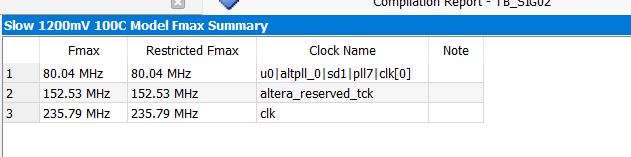
This is the highest operating frequency supported by the chip after program compilation. It can be seen that u0 can only reach a maximum of 80MHz, while I was using a 50MHz onboard crystal oscillator, which was then multiplied by PLL to 100MHz. Therefore, 80MHz cannot meet the actual usage requirements of the chip.
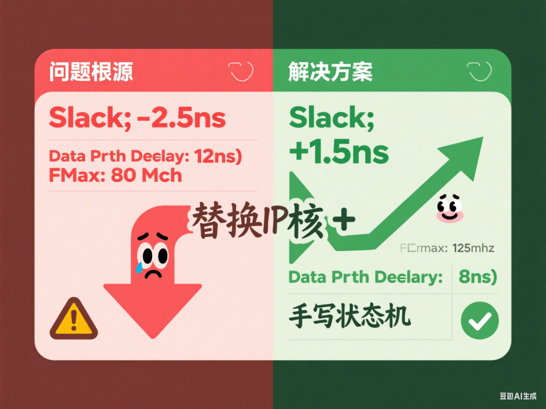
The main reason for this issue is that the program written by Teacher B used the official IP core for multiplication and division operations. Although these IP cores are convenient to use, they consume a lot of resources and can easily lead to a reduction in the chip’s maximum operating speed.
While copying Teacher B’s program, I was too careless and did not pay attention to the impact of timing constraints.
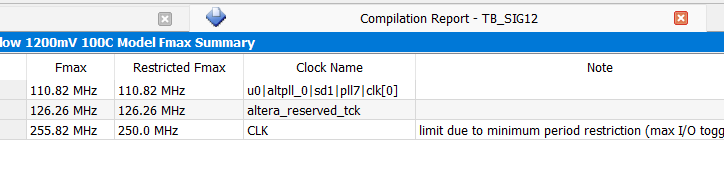
Once the problem was identified, the solution became much easier. I replaced the IP core required for multiplication and division operations and manually wrote a program based on actual needs, implementing it in a state machine manner, with sufficient response time. After compilation, the maximum supported frequency was also increased:
For a long time, I did not have a clear understanding of the role of timing constraints. The reason is simple: I learned FPGA in a non-traditional way, and my early programming principle was just to make it work.
In reality, whether it can work or not requires long-term stable testing, which is a serious matter.
Through this experience, I have gained a more intuitive understanding of the function of timing constraints in FPGAs.
That’s all for now!