Click the blue text above
Follow us!

The front camera is a critical component of the Advanced Driver Assistance Systems (ADAS), especially considering the new car crash test requirements that standardize automatic emergency braking and frontal collision avoidance as essential functions of vehicles. The front camera assists in enabling other ADAS functions such as adaptive cruise control, pedestrian detection, lane-keeping assistance, and traffic sign recognition.
Figure 1 illustrates how cameras are used for object detection to enable ADAS functions.
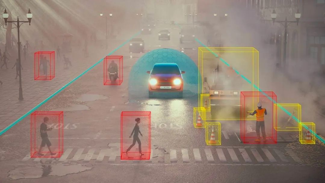
Figure 1: Real-time processing using a camera
To perform processing tasks such as visual preprocessing, depth and motion acceleration, or AI network processing to support ADAS functions, the System on Chip (SoC) in the system requires efficient power. When designing the ADAS front camera, the following four power challenges arise.
Challenge 1: Compact Size Solutions
Since the front camera is located on the windshield, strict size requirements are imposed. The camera module can include one or two cameras: one to provide a wider field of view or higher resolution, and the other for observing greater distances.
While most applications on the market use a single camera module, dual-camera modules are becoming increasingly popular to better observe the vehicle’s surroundings and achieve a higher level of autonomy. High-resolution and higher frame rate camera modules are also a trend. As camera performance improves, the size of the camera module itself is continuously shrinking, typically measuring 18mm x 18mm.
Remote camera modules use serializer/deserializer (SerDes) links to transmit data from the camera module to the Electronic Control Unit (ECU). The front camera module is co-located with the front camera ECU, using the Camera Serial Interface (CSI)-2 to send data to the ECU circuit board. The input power voltage for the front camera module can be as low as 5V, while remote camera modules powered by coaxial cables typically use 9V. The multi-channel Power Management IC (PMIC) on the front camera module sub-board uses low-voltage input to power the imager as well as all other processing tasks on the camera module. Before streaming data to the ECU via CSI-2, processing can be performed by an onboard microcontroller (MCU). The MCU on the camera module can perform pixel-level image signal processing, or this processing can be done by a separate chip. Notably, the SerDes chipsets commonly found in remote camera modules do not require power rails. A low-voltage PMIC with an appropriate number of power rails can power the image sensors and other peripherals on the camera module, helping to achieve the small space required by these systems.
Figure 2 shows the system block diagram of the front camera. This system is typically located behind the windshield near the rearview mirror and includes the front camera ECU that performs processing and the camera module that houses the image sensor.
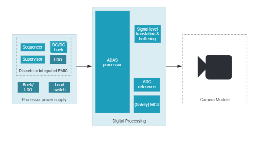
Figure 2: Front camera system block diagram
The vision processors used in front camera applications feature dedicated hardware accelerators known as vision processing accelerators, as well as depth and motion perception accelerators capable of detecting edge objects. Additionally, these processors may have artificial intelligence (AI) capabilities and come equipped with dedicated matrix multiplication accelerators to aid in deep learning. Given such a large processing load, the PMIC must be able to meet the current requirements of the processors without increasing the size of the solution.
The PMIC should have excellent transient response to meet the transient load requirements of the AI processors and utilize smaller output capacitance to maintain a compact solution size. Integrated buck regulators, low-dropout regulators, load switches, voltage monitors, sequencers, watchdog timers, fault signaling modules, and additional general-purpose I/Os contribute to reducing the size of the solution. This leads to a significant reduction in size compared to solutions with multiple discrete components that would increase overall size and cost.
The commonly used power tree architecture in this application builds two-stage power conversion, which helps maintain overall efficiency and keep component temperatures within acceptable ranges. In this power tree architecture, the front-end DC/DC converter steps down the 12V battery voltage to an intermediate voltage regulated by the multi-channel PMIC (e.g., 5V or 9V). The front-end DC/DC converter should be chosen as a wide input voltage buck converter capable of supporting sudden drops in battery voltage from 12V to 3V and surges up to 36V transient voltage.
Challenge 2: Functional Safety
Functional safety is particularly important since the front camera is involved in automatic emergency braking and adaptive cruise control. The front camera system typically has Automotive Safety Integrity Level (ASIL) B requirements. This means that the PMIC power for the processor must be able to meet ASIL B requirements, thereby helping to achieve overall system-level functional safety requirements.
Here are some features that an ASIL B PMIC should possess:
-
Voltage monitors for PMIC power rails
-
Additional monitors for detecting other power rails in the system
-
Bandgap redundancy
-
Watchdog timers for detecting software faults
-
Error signaling monitors for detecting hardware faults
Challenge 3: Low Cost
As front cameras are widely adopted in passenger cars and light commercial vehicles, it is crucial to reduce the cost of camera systems. It is expected that by 2028, the sales of front camera systems will exceed 70 million units, making them a common ADAS application in vehicles.
High volume will put cost pressure on tier-one suppliers, which in turn puts pressure on semiconductor suppliers. By reducing the bill of materials, selecting integrated components, choosing the right technology node, and maintaining low device costs, the overall system cost can be lowered. The compact size of the PMIC, which integrates multiple power components, helps achieve these advantages and optimize costs.
Challenge 4: Thermal Performance
Since the front camera is located on the vehicle’s windshield, it is exposed to high temperatures under normal operating conditions. Heat can cause thermal noise and lead to poor image quality, especially in low-light conditions. The front camera requires a small printed circuit board area, and the heat generated by the camera in the module further increases the thermal challenges of this application. Optimizing the thermal performance of the system is crucial to accommodate various operating conditions. Good thermal performance of the PMIC helps keep the circuit board at low temperatures.
Conclusion
Adding a PMIC to the ADAS front camera can mitigate the four challenges described in this article and enhance the efficiency and thermal performance of the front camera system. Depending on specific system requirements, Texas Instruments (TI) AM62A-Q1 or TDA4AL-Q1 processor series can help streamline your front camera design process.
For more online technical support, please visit the TI E2E™ Chinese Support Forum (e2echina.ti.com).


Click “Read the original text”, to learn more about TI TDA4AL-Q1 products!