A multimeter is currently the most popular and commonly used portable measuring instrument that can perform various measurement tasks, replacing certain specialized instruments to accomplish multiple electronic and electrical measurement tasks, achieving multiple uses with one device.
Classification of Multimeters
Multimeters are classified into analog (pointer type) and digital types. Common analog multimeters include MF4, MF10, MF35, MF47, MF500, etc., while common digital multimeters include models 177C, 179C, DT9205M, DT830B, DM8345, VC890, etc.
Analog multimeters are easy to use, inexpensive, and stable in performance, not easily affected by external environments and measured signals, allowing for an intuitive observation of measurement trends.
Digital multimeters offer high testing accuracy, a wide measurement range, clear displays, and accurate readings, and can also measure capacitance and small resistance accurately.
Both types of multimeters have their strengths and cannot completely replace each other during use; they can complement each other when used together.
1. Analog Multimeter
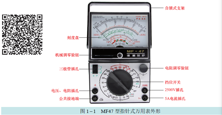
Precautions for Using Analog Multimeters
(1) Before using the multimeter, familiarize yourself with the functions of each switch, knob (button), measurement socket (terminal), dedicated ports, and instrument accessories (high-voltage probes, etc.), and understand the measurement values corresponding to each scale line.
Before measuring, clarify what and how to measure, then rotate the range switch to the corresponding measurement item and range. If the voltage or current size to be measured cannot be estimated in advance, first set it to the highest range, then gradually lower it to an appropriate range, ensuring the pointer stays within 20%-80% of the scale line’s starting position (readings are accurate within this range).
Before each measurement, check whether the measurement item and range switch are correctly positioned to avoid damaging the multimeter by mistakenly using the current or resistance range to measure voltage.
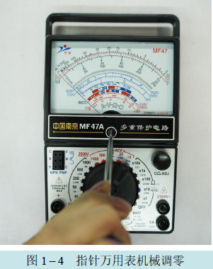
(2) The multimeter can be placed horizontally or vertically; improper placement may cause measurement errors. After placing it according to regulations, if the pointer does not point to zero, adjust the zero adjustment knob to bring the pointer to zero. When reading, your line of sight should be aligned with the pointer to avoid parallax. If the dial has a mirror, the pointer seen should align with its reflection.
(3) Precautions When Measuring Voltage.
1) The multimeter should be connected in parallel across the circuit to be measured. When measuring DC voltage, pay attention to the polarity to prevent the pointer from deflecting backward. If the polarity is unknown, connect one probe first, then quickly touch the other probe to the test point; if the pointer deflects left, the connection is incorrect, and the red and black probes should be swapped for measurement. If a digital multimeter is available, it is best to use it for measurement.
2) The basic error of the voltage range is expressed as a percentage of the full scale, so the closer the measurement value is to the full scale, the smaller the error. Generally, the selected range should be such that the pointer deflects to more than half of the full scale.
3) When measuring voltages above 100V, safety must be observed; develop the habit of using one hand for operation. Secure one probe to the common point of the circuit to be measured, and use the other probe to touch the test point, which helps concentrate attention and avoid electric shock while reading the display. When measuring high voltages over 1000V, ensure the plug is securely inserted to prevent arcing due to poor contact or accidents from the plug falling out.
When measuring high voltage, use high-voltage probes to ensure safety. High-voltage probes come in DC and AC types, both with attenuators inside to reduce the measured voltage by 10 or 100 times. High-voltage probes are equipped with hooks or alligator clips for secure attachment. It is strictly forbidden to rotate the range switch while measuring high voltages (e.g., above AC 220V) to avoid arcing and damaging the switch contacts.
4) When measuring high internal resistance power supply voltages, choose a higher voltage range to increase the internal resistance of the voltage range; although the pointer deflection angle may be smaller, the measurement result will be more accurate.
5) If the DC voltage range is mistakenly used to measure AC voltage, the pointer will not move or will slightly oscillate without deflection. If the AC voltage range is mistakenly used to measure DC voltage, the reading will be approximately double.
(4) Precautions When Measuring Current.
1) When measuring current, connect the multimeter in series with the circuit to be measured; do not connect the two probes across the circuit to prevent damaging the multimeter.
2) When measuring DC current, pay attention to the current’s polarity. If both the internal resistance of the power supply and the load resistance are small, choose a larger current range to reduce the internal resistance of the current range and minimize its impact on the circuit being measured.
(5) Precautions When Measuring Resistance.
1) When measuring resistance, connect the two probes across the resistor. It is strictly forbidden to measure resistance while the circuit is powered, as this is equivalent to applying an external voltage, leading to inaccurate measurements and potential damage to the multimeter, even causing electric shock hazards.
2) Every time the resistance range is changed, the zero point for the ohm range should be readjusted. If the R × 1Ω range has been used continuously for a long time, the zero point should also be readjusted. If the R × 1Ω range cannot be adjusted to zero, replace the battery immediately, ensuring the correct polarity; if a new battery is not available, subtract the zero point error from the measured value.
3) The scale of the resistance range is nonlinear; the closer to the high resistance end, the denser the scale, and the greater the reading error. Therefore, during measurement, keep the pointer near the middle value, where the error is minimal.
4) When measuring electrolytic capacitors with the resistance range, ensure to short-circuit and discharge the positive and negative terminals first to prevent the stored charge from damaging the meter. Since the multimeter R × 10Ω range uses two 1.5V and 9V batteries in series, it is not advisable to use this range for measuring low-voltage (6V) electrolytic capacitors.
5) When measuring the equivalent resistance of polarized components such as diodes, transistors, voltage regulators, and field-effect transistors, pay close attention to the polarity of the probes. In the resistance range, the black probe connects to the positive terminal of the internal battery, and the red probe connects to the negative terminal. If the polarities of the probes are reversed, the measurement results will differ. Using different ranges to measure their equivalent resistance will yield different results, which is normal due to nonlinear devices presenting different equivalent resistances for different test currents.
6) When measuring large resistances, do not hold the conductive part of the probes with your hands to avoid affecting the measurement results.
7) During measurement, do not let the two probes touch (short-circuit); leaving miscellaneous items on the workbench can easily cause probe short-circuits, which will waste battery power and shorten its lifespan.
(6) Precautions When Measuring Audio Levels.
In the past, communication lines in China used a characteristic impedance of 600Ω for overhead lines, and the input and output impedances of communication terminal equipment and measurement instruments were designed according to 600Ω. Therefore, the multimeter level scale is based on the AC 10V range and drawn according to the 600Ω load characteristic. Zero level indicates a power of 1mW generated at 600Ω impedance, corresponding to a voltage of 0.775V.
The principle of measuring levels is the same as measuring AC voltage. If the load R of the circuit being measured does not equal 600Ω, it should be corrected using the following formula: actual dB value = multimeter dB reading + 10 × lg (600/R).
2. Digital Multimeter
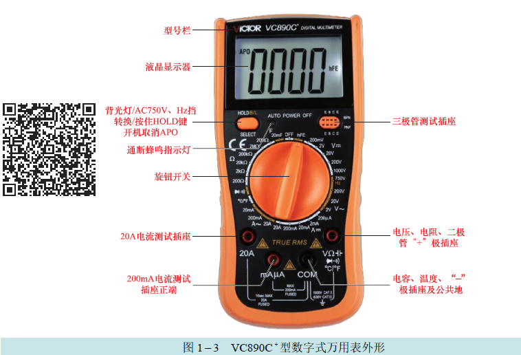
Precautions for Using Digital Multimeters
1. Fully Understand Multimeter Performance
(1) Read the user manual carefully before use.
(2) Since most European and American countries use 60Hz AC power, imported digital multimeters have strong resistance to 60Hz interference but are less effective against 50Hz. By changing the clock frequency of the A/D converter to be a whole multiple of 20ms (the period of 50Hz), it can be used normally.
(3) Digital multimeters cannot reflect continuously changing quantities. Their testing process is: sampling → A/D conversion → counting display, so they cannot reflect the continuous change of electrical quantities. If you want to check the charging and discharging process of an electrolytic capacitor, use an analog multimeter. Using a digital multimeter to check if a flip-flop is continuously flipping is also not intuitive.
(4) Digital multimeters have poor frequency characteristics and can generally only measure low-frequency signals from 45Hz to 1kHz. When the operating frequency exceeds 2kHz, the testing error rapidly increases. If high-frequency signals need to be tested, choose a model equipped with high-frequency test heads.
2. Precautions When Measuring Voltage
(1) Digital multimeters have automatic conversion and display polarity functions; when measuring DC voltage, the probes can be connected in parallel with the circuit without considering polarity.
(2) If the size of the voltage to be measured cannot be estimated, select the highest range for a test, then choose an appropriate range based on the situation. If the display shows only “1” while other digits are off, it indicates the instrument has exceeded its range, and a higher range should be selected.
(3) The maximum input voltage for the VC890 digital multimeter is generally 1000V for the DC range and 750V for the AC range. When the AC voltage to be measured has a DC component superimposed, the sum of both voltages must not exceed the maximum input voltage of the AC range; if necessary, add an external capacitor to block the DC component from entering the multimeter.
(4) The input resistance of the voltage range on digital multimeters is very high, typically 10MΩ. When the two probes are open, external interference signals can easily enter through the input, causing the display to show irregular numbers at low levels; this is normal.
Interference sources include operating fans, refrigerators, air conditioners, televisions, fluorescent lights, and electrical sparks. All the above interferences belong to high internal resistance signals; as long as the internal resistance of the voltage source being measured is low, the interference signals will be shorted and will not affect the measurement.
However, if the measured voltage is low and its internal resistance exceeds 1MΩ, the multimeter will still introduce external interference. If necessary, change the probe leads to shielded cables and connect the shield to the “COM” socket to ground to eliminate interference.
(5) Using the “ACV” range to measure DC voltage or the “DCV” range to measure AC voltage will display “000” or show jumping numbers at low levels; the latter is caused by the input of external interference signals and is normal.
(6) Do not use the DC voltage range of the multimeter to test its own 9V stacked battery voltage.
4. Precautions When Measuring Current
(1) When measuring current, make sure to connect the two probes in series with the circuit being measured without considering polarity, as the digital multimeter can automatically convert and display the current polarity.
(2) If the internal resistance of the current source being measured is very low, choose a higher current range to reduce the voltage drop across the shunt resistance, improving measurement accuracy.
(3) If the input current exceeds 200mA, insert the red probe into the “20A” socket. This socket generally does not have a protective circuit, and the measurement of large currents should not exceed 10 seconds to prevent the shunt resistance from heating and changing its resistance value, affecting measurement accuracy.
5. Precautions When Measuring Resistance
(1) When measuring resistance, testing diodes, and checking circuit continuity, the red probe should be inserted into the “V·Ω” socket or “mA/V/Ω” socket, positive; the black probe should be inserted into the “COM” socket, negative. When testing polarized components such as electrolytic capacitors, diodes, transistors, and light-emitting diodes, pay close attention to probe polarity.
(2) It is strictly forbidden to measure resistance while powered; direct measurement of the internal resistance of batteries is also not allowed, as this applies an input voltage to the multimeter, rendering the measurement meaningless and potentially damaging the multimeter.
(3) The testing current provided by the resistance range of digital multimeters is relatively small, so when measuring the forward resistance of diodes, the value obtained will be several times, even dozens of times higher than that measured with an analog multimeter; this is normal. In this case, use the diode range to measure the forward voltage drop of the PN junction for accurate results.
(4) When measuring low-value resistances with the 200Ω resistance range, short the two probes first to measure the lead resistance (generally 0.1 to 0.3Ω), then subtract this value from the measurement result to obtain the actual value. For ranges from 2kΩ to 20MΩ, the lead resistance can be ignored.
(5) Due to different testing voltages and currents, measuring the same nonlinear component (such as thermistors or semiconductor diodes) with different resistance ranges will yield different resistance values; this is normal.
(6) Do not use digital multimeters to measure the equivalent resistance of the human body. There is distributed capacitance between the body and the ground, which can induce strong 50Hz AC interference signals, sometimes reaching several volts to tens of volts, which can easily exceed the range when holding both probes. Similarly, do not touch the probes when measuring the resistance of components.
6. Precautions When Using Other Functions
(1) When measuring polarized electrolytic capacitors, the polarity of the capacitor socket should match that of the capacitor being measured. The capacitor must be shorted to fully discharge before measurement; otherwise, the stored charge could damage the internal integrated circuit of the meter.
(2) When using the hFE socket to measure the current amplification factor of small power transistors, ensure the three electrodes of the transistor and the selected range (PNP or NPN) are not confused. Because the testing voltage is low, the hFE socket provides a very small base current (generally 10μA), and the measured transistor operates under low voltage and low current conditions, making the measurement result only for reference.
(3) The temperature measurement range (TEMP) of digital multimeters generally requires nickel-chromium-nickel-aluminum or nickel-chromium-nickel-silicon thermocouples, with a resolution of 1°C and an accuracy of ±1.0% to ±1.5%. The VC890C+ digital multimeter has a temperature measurement range of -40 to 1000°C, allowing direct reading of temperature values from the screen.
Selecting and Using Multimeters Reasonably
1. Selecting Multimeters
There are many models of multimeters, and the functions vary between different models. Generally, multimeters with high precision, sensitivity, multiple functions, and larger sizes are of higher quality and price. Therefore, when selecting a multimeter, pay attention to the following aspects:
(1) If your work mainly involves weak currents, such as home appliance repairs, ensure the multimeter’s sensitivity is not less than 20kΩ/V; otherwise, the impact on the circuit during DC voltage testing will be too great, resulting in inaccurate test data. Ideally, it should have a 100V range; if frequent on-site repairs are needed, choose a slightly smaller multimeter; if not often on-site, the commonly used MF47 multimeter can be selected.
(2) If your work mainly involves strong currents, such as repairing electrical equipment or three-phase AC motors, ensure the selected multimeter has an AC current range.
(3) When using an analog multimeter, check the meter head. After mechanical zeroing, when the meter is slightly shaken in the horizontal and vertical directions, the pointer should not have significant oscillation; when placed horizontally and vertically, the pointer deflection should not exceed one small division; when rotated 360°, the pointer should remain near the zero position. If these requirements are met, it indicates that the meter head is functioning properly in terms of balance and damping.
2. Reasonable Use of Multimeters
Analog and digital multimeters differ in structure and principle, leading to performance differences; therefore, choose different types of multimeters reasonably based on actual needs and pay attention to complementing each other’s strengths and weaknesses for combined use.
(1) Situations Where Digital Multimeters Are Preferable
1) When measuring voltage online, the higher the internal resistance of the multimeter, the better, as this minimizes its impact on the circuit. Therefore, digital multimeters are the first choice, especially for measurements requiring high precision, such as tuning voltages in high-frequency circuits, oscillation tubes in switching power supplies, and digital output circuits.
2) When measuring small resistances, it is advisable to use a digital multimeter due to its high input impedance, which does not attenuate the input signal. Analog multimeters can fully handle large resistance measurements. However, for high precision resistance measurements, such as measuring current-limiting resistors or low-resistance components in a collection circuit, only digital multimeters should be used.
3) To accurately measure capacitance, only digital multimeters should be used. When measuring capacitance with the resistance range of an analog multimeter, it can only rely on experience or rough comparison to judge its capacity. For capacitors below several hundred picofarads, the multimeter will not respond on the R × 10kΩ range, and for capacitors above 2000pF, the multimeter can only measure on the R × 10kΩ range, judging capacitance by the pointer’s swing. When testing the voltage or soft breakdown of capacitors, the battery voltage of the analog multimeter’s R × 10kΩ range is relatively high, close to the operating conditions of some capacitors, which can easily damage them.
(2) Situations Where Analog Multimeters Are Preferable
1) To determine whether a capacitor is leaking, using an analog multimeter is more convenient.
2) For testing continuous changes in electrical quantities and processes, such as the charging and discharging process of capacitors, thermistors, and photodiodes, analog multimeters are more intuitive and user-friendly.
3) Both types of multimeters can test diodes and transistors. Digital multimeters can accurately measure the voltage drop across PN junctions and can also accurately measure the hFE value of small power transistors. However, for estimating the breakdown voltage and penetration current of diodes and transistors, using an analog multimeter is preferable. When measuring light-emitting diodes, digital multimeters can determine both their functionality and polarity.
4) When measuring integrated circuits and thick film circuits with the resistance method, it is advisable to use an analog multimeter.
This article is adapted from “From Novice to Master: Testing Electronic Components with Multimeters.”
Editor: Tu Peng