 Reminder: Click the top↑ ‘Electric Vehicle Resource Network’ to subscribe for free.
 Electric Vehicle Resource Network News:
Core Tips
The electric propulsion technology requires the integration of a new architecture power transmission system in vehicles, which necessitates in-depth multidisciplinary research on the corresponding system components.
“Save our planet, keep it free from pollution!” This is the unanimous call from scientists and visionaries around the world to reduce greenhouse gas emissions. Cars powered by fossil fuel engines are the main culprits. Although there are many alternative technologies to drive vehicles, the only viable solution currently is electricity.
The electric propulsion technology needs to integrate a new architecture power transmission system in vehicles, which requires in-depth multidisciplinary research on the corresponding system components. The electric vehicle system consists of electric motors, power converters, and energy storage devices such as lithium-ion batteries. This new architectural system must be optimized to maximize system efficiency, allowing the vehicle to achieve the longest driving distance on a single charge. The development of electronic technology provides significant impetus for reducing gas emissions in transportation.
Electric Vehicles (EV) and Hybrid Electric Vehicles (HEV)
Electric vehicles run on batteries, and hybrid electric vehicles do as well, but they also utilize a fossil fuel ignition engine as an auxiliary. For these vehicles to be successful and have a bright future, energy efficiency is key. Therefore, an intelligent power management mechanism is needed to maximize the efficiency of converting battery energy into mechanical driving force for the wheels, thereby increasing the driving distance on a single charge without increasing carbon emissions, ideally significantly reducing carbon emissions.
Silicon Carbide (SiC) Power in Electric Vehicles
The weight, size, and cost of electric vehicles, as well as the driving distance per charge, are directly related to the efficiency of the power conversion system. SiC power components are very suitable for operation in the high-temperature environments commonly found in vehicles. Let’s take a closer look at how SiC power components improve system efficiency.
Lighter weight means extended mileage. A typical way to reduce the weight, cost, and size of the power conversion system is to increase the switching frequency of the switch-mode power supply. We all know that at higher frequency points, the size and weight of active components such as inductors, capacitors, and transformers can be reduced. Therefore, let’s quickly adopt SiC solutions.
Although silicon (Si) power components can also operate at high frequencies, the advantage of SiC is its ability to handle much higher voltages than Si. SiC is a wide bandgap (WBG) semiconductor component, and a wider bandgap means a higher critical electric field (the blocking voltage in the off state). The high voltage capability of wide bandgap SiC components allows them to have lower conduction resistance, resulting in faster switching speeds and unipolar operation. Part of the principle is that its carrier frequency needs to be accelerated to a higher speed (higher kinetic energy) to overcome the wider bandgap.
While gallium arsenide (GaA) and gallium nitride (GaN) also have high critical electric fields and are improved components for high-power solutions, SiC has other advantages. These include higher maximum operating temperatures, a very high Debye temperature, high thermal conductivity (in polycrystalline SiC), fast switching in the electric field, low resistivity due to high carrier saturation velocity, lower production costs due to easier generation of silicon dioxide (SiO2), and stronger radiation hardening due to higher threshold energy.
SiC components have many key applications in electric vehicles. Existing electric traction drive systems can convert 85% of electrical energy into mechanical energy to drive the wheels, which is quite efficient, but SiC can also help improve this efficiency. Power converters can benefit from efficiency improvements because they can transfer battery energy to the engine and can be used in battery charger circuits and any required auxiliary power supplies (Figure 1).
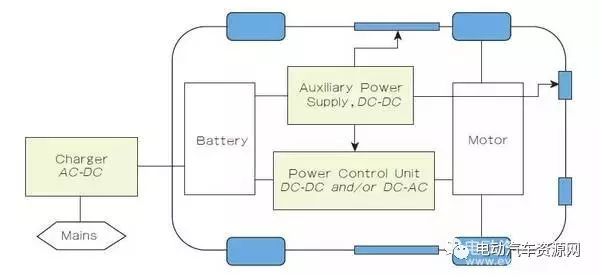
▲Figure 1 SiC power components have many uses in electric vehicles
SiC power supplies that convert 750V to 27V for low-voltage electric vehicles are a great example of using SiC power components to enhance electric vehicle efficiency. This architecture improved efficiency from 88% to an astonishing 96%, reduced size and weight by 25%, and did not require fans to cool excess heat compared to Si solutions. Table 1 shows some important applications of SiC power components in electric vehicles.
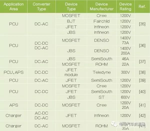
Table 1 Some applications of SiC in the electronic architecture of electric vehicles. (PCU refers to Power Control Unit; APS refers to Auxiliary Power Supply) (Table source: 2015 Tenth International Conference on Ecological Vehicles and Renewable Energies)
GaN Power in Electric Vehicles
GaN also plays an essential role in the power improvements of electric vehicles. Insulated Gate Bipolar Transistors (IGBTs), widely used in motor drives and DC/DC control, have traditionally been based on Si products. The switching times of these designs typically fall in the range of 10k to 100kHz, while GaN components can achieve switching times in the nanosecond (ns) range and can easily operate in automotive environments at 200℃.
Like SiC, GaN components can also reduce the size of inductors, capacitors, and transformers in the power architecture due to their higher switching speeds, and can reduce overall volume and weight due to the smaller size of passive components.
We will analyze their effectiveness based on the chemical composition of electric vehicle batteries, such as lithium-based chemistries and high energy density nickel-metal hydride (NiMH) batteries. As mentioned in the previous section on SiC components, improving the efficiency of the power conversion architecture is also necessary to achieve longer driving distances on a single charge.
Switching speeds and minimum conduction resistances of Si components have reached their maximum limits, and GaN seems to be a viable option to surpass these limits. Experiments show that if the switching frequency can be increased fivefold, the size of inductors and capacitors can be reduced to one-fifth. Today’s GaN technology can support very high speeds.
GaN power components excel in four key areas: high-temperature operation, higher breakdown voltage, low conduction resistance, and suitable switching speeds at higher operating frequencies. These advantages are similar to those of GaN and SiC, but there are two distinctions: LEDs and RF transistors have always used GaN; many Si processes are compatible with GaN processes, which lowers wafer costs and process costs compared to the higher substrate costs of SiC.
Since reliability issues were addressed as early as 2003, today’s technology has successfully put the first GaN High Electron Mobility Transistor (HEMT) components into production. These are normally-on components, so a gate voltage of 0V will create a conductive state, while any voltage below 0V will turn off the component. Early versions used SiC substrates; once Si substrates can be perfectly combined with GaN, production costs can be significantly reduced. In 2014, a new cascaded architecture was implemented to convert normally-on components into normally-off components.
Since then, driving technologies have made significant advancements, and the level of integration has increased, leading to significant improvements in power inverters. GaN components also perform exceptionally well in electric vehicle battery chargers, which consist of AC/DC converters and DC/DC converters. This combination serves as a Power Factor Controller (PFC) (Figure 2).
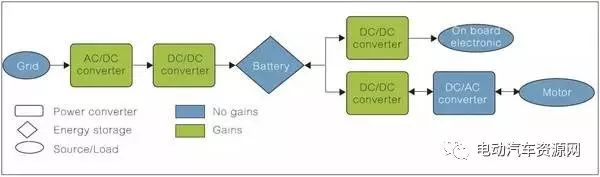
▲Figure 2 Typical power architecture in electric vehicles
Utilizing GaN along with the higher switching speeds of GaN HEMT can achieve smaller passive components. Increased frequency leads to lower ripple currents through smaller inductors, thus improving power factor and resulting in smaller, less costly capacitors. Lower ripple currents also reduce stress on capacitors, thereby enhancing their reliability and lifespan.
In recent years, the reliability of GaN has been elevated to a very high standard, which is key to its use in vehicles.
Utilizing Hybrid Electric Vehicle Transmission Systems to Reduce Greenhouse Gas Emissions
Currently, approximately 72% of transportation emissions are generated by cars on the road. Improving the design of hybrid electric vehicle transmission systems to enhance their efficiency is a primary means of reducing emissions. One method is to enhance the efficiency of the DC-link voltage control architecture, which means first improving the efficiency of the power converters in series hybrid electric vehicle transmission systems.
The DC-link typically connects three transmission systems: a primary power source consisting of three-phase rectifiers; a secondary power source consisting of dual active bridge (DAB) DC/DC converters; and a propulsion load consisting of three-phase inverters (Figure 3), which are related to series hybrid electric vehicles.
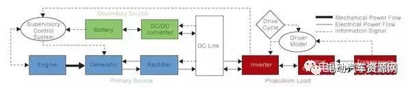
▲Figure 3 Block diagram of transmission systems in hybrid vehicles
In designs where the DC-link and battery voltages are not equal, an intermediate solution in the DC/DC converter is necessary. An IEEE paper titled “Voltage Control for Enhanced Power Electronic Efficiency in Series Hybrid Electric Vehicles” describes many methods for researching different architectures and schemes for various DC-link voltages and DC/DC converter controls.
The following will discuss the proportional control law, which is used to control the dynamic DC-link voltage to achieve phase shifts between the gate switching waveforms of the DAB DC/DC converter. This converter is located between the DC-link and the battery in the series hybrid electric vehicle transmission system, as shown in Figure 4. In this case, the controller reduces energy losses in the DC/DC converter and the entire transmission system.
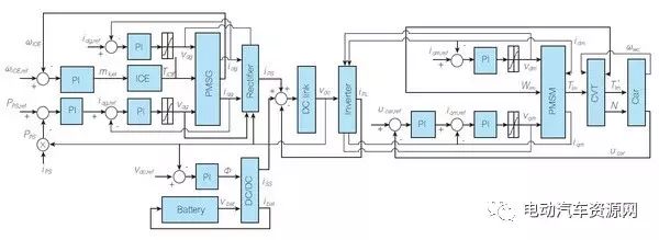
▲Figure 4 Interconnection diagram of the hybrid vehicle transmission system in the control schematic
The engine (ICE), continuously variable transmission (CVT), permanent magnet synchronous motor (PMSG), or the primary power source of the hybrid vehicle, and the permanent magnet synchronous motor (PMSM) or the propulsion load of the hybrid vehicle are all key components of the system shown in the figure.
In this model, the diesel engine is the primary power source of the hybrid vehicle, and the DC battery is the secondary power source. The management control system (SCS) controls the power ratios provided by these two power sources based on the state of charge (SOC) of the battery and the load of the motor.
In fact, in this series hybrid electric vehicle, the DC-link voltage will impose conditions on the ideal operating region of the PMSM and PMSG corresponding to the unit modulation index, thus allowing the system to avoid over-modulation states that lead to signal distortion and reduced system efficiency. Keeping the modulation index close to 1 can enhance the overall efficiency of the power circuits in the transmission system, thereby maximizing the efficiency of the inverters and rectifiers, as the switching process is the main factor of efficiency loss, thus reducing switching voltage can improve efficiency.
This continuous zero-voltage switching (ZVS) mechanism, which can minimize power losses, is most suitable for vehicles with a high hybrid factor (HF), especially in urban environments. The hybrid factor refers to the ratio of installed power from the power source to the total installed power. This hybrid factor affects fuel consumption in hybrid vehicles.
Automobile Inverters
The main power inverter controls the motors in the power transmission system and is an important device in hybrid and electric vehicles. The power inverter is akin to the engine management system (EMS) in conventional vehicles, determining driving behavior. This inverter is suitable for any motor type, such as synchronous, asynchronous, or brushless motors, and is controlled by an integrated electronic PCB designed by automotive manufacturers to minimize switching losses and maximize thermal efficiency. Another function of the inverter is to capture energy released from regenerative braking and feed it back to charge the battery. The driving range of hybrid and electric vehicles is directly related to the efficiency of the main inverter (Figure 5).
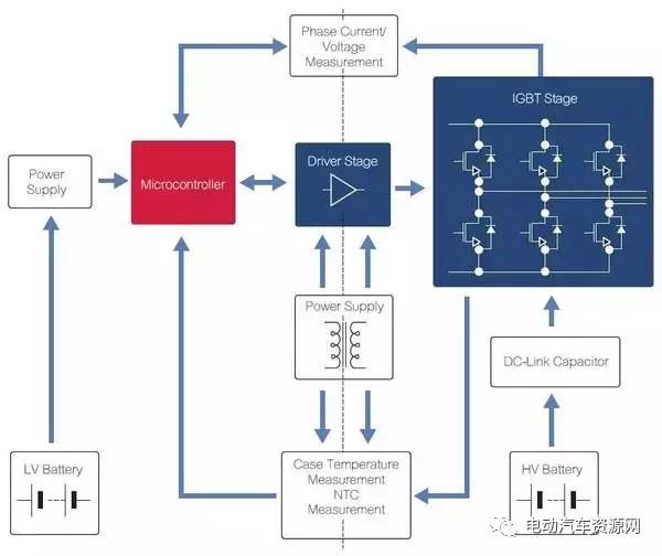
▲Figure 5 Framework diagram of Infineon’s main inverter in hybrid and electric vehicles. (Image source: Infineon)
Dual Voltage Battery Systems
Managing batteries in hybrid and electric vehicles requires high-voltage technology. A dual voltage system that combines 12V and 48V batteries requires bidirectional DC/DC conversion, as shown in Figure 6, for circuit protection and supporting architectural functions.
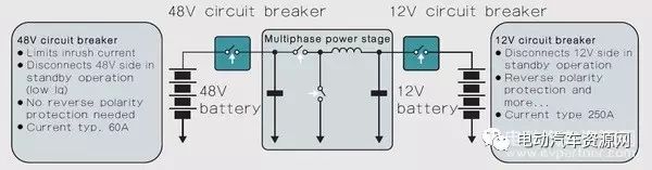
▲Figure 6 Bidirectional DC/DC converter from 48V to 12V
Additionally, automotive architecture designs typically include a single-phase 3.5kW or 7kW onboard charger module (OBCM) for charging electric or plug-in hybrid vehicles (PHEV) from the grid. Conversely, electric vehicles and plug-in hybrid vehicles can serve as energy sources and can be integrated into smart grids that incorporate renewable energy as energy storage devices. When working with smart grids, intelligent charging and discharging of electric vehicles and plug-in hybrid vehicles must be considered, which is why OBCMs must be bidirectional DC/DC chargers.
The optimal architecture for this design is a boost series resonant bidirectional topology, as shown in Figure 7. It operates above the resonant frequency and has zero-voltage switching capability, achieving maximum power transfer performance at the minimum switching frequency point. Compared to unidirectional power flow converters, this technology replaces diode rectifiers with MOSFET rectifiers. This solution also offers higher efficiency and a wider battery capacity. A major drawback of this architecture shown in Figure 7 is that the rectifier bridge has significant losses when turned off, an issue that must be addressed in future designs.
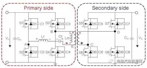
Figure 7 Designers sometimes use modulated DAB converters to control simple high-frequency isolation, with the advantage of lower component stress; the main disadvantage is that ZVS cannot be extended across the entire output range, especially under light load conditions. This figure shows that the boost series resonant bidirectional converter is a better architecture.
Delphi Integration and Wiring
Delphi has integrated all the modular components discussed in this article along with several other power electronic components for hybrid electric vehicles (Figure 8), which is impressive.

▲Figure 8 High integration achieved by Delphi in hybrid/electric vehicles
Using appropriate internal connectors in hybrid and electric vehicles is also crucial (Figure 9).
▲Figure 9 Key element in hybrid/electric vehicles is minimizing mass
Delphi has made significant innovations in low-profile cable technology, insulation materials, and lighter copper substitutes (such as aluminum or some special proprietary alloys). (Image source: Delphi)
Electric Wheel Drive Systems
The article “Design and Implementation of an Electric Drive System for In-Wheel Motor Electric Vehicle Applications” recommends a motor drive system suitable for hybrid and electric vehicles, and a Matlab SIMULINK model for motor drive hybrid vehicles providing computational performance has been successfully developed. Two 14kW DC brushless motors were designed and manufactured according to the literature, installed within the wheel rims of hybrid vehicles.
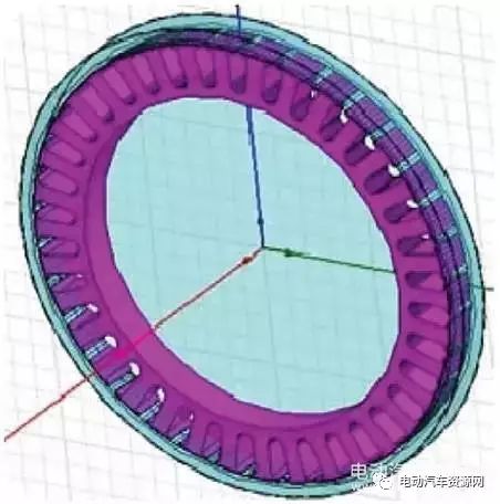
▲Figure 10 Brushless DC motor diagram for one rear wheel
Additionally, two independently driven rear wheels are also installed on a Fiat Linea vehicle. By detecting the angle of the steering wheel, electronic control technology replaces the mechanical differential. Communication between the electric drive control system and the electronic control unit (ECU) of the vehicle occurs via the CAN bus, successfully cascading the electric drive rear wheels and the ICE-driven front axle.
This design chose a brushless DC motor with a central coil, as it has a very low power-to-weight ratio and high efficiency, and is easy to control.
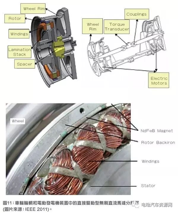
▲Figure 11 Breakdown diagram of direct drive brushless DC motor in wheel rim and generator device
Driver
The power driver for the brushless DC motor consists of an integrated power module (IPM), an 8-bit microcontroller, and an electronic control system. Driver software development is used for IGBT commutation control and pulse width modulation (PWM) voltage control. The system has optical isolation, current and temperature protection, and also embeds speed, current, and voltage sensors.
In summary, this article presents some recent developments in power management for electric and hybrid vehicles. More developments are sure to emerge in the future, further improving these systems for the benefit of the planet.
┃Content Source:EDN Taiwan
⊙2016 New Energy Passenger Car Sales Ranking Released, Guess Who Will Be the Champion?
⊙[EV Jianghu·Bounty Notice] New Energy Vehicles, Your Jianghu, You Speak!


Click below to read the original text
