The PLC control cabinet is the core of industrial automation systems, and the quality of its wiring directly determines the stability and operational safety of the system. This article is based on GB 50054-2011 “Low Voltage Distribution Design Specification” and IEC 60947-5-1 International Standard, providing a detailed analysis of the configuration standards, safety significance, and practical points of 15 key wiring parameters, along with schematic illustrations, to offer compliance and safety guidelines for engineering personnel.
1. Power Voltage Level Configuration
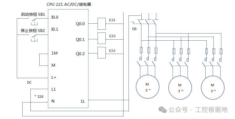
Core Requirement: The PLC system power supply must be independently sourced from a stable main line, avoiding shared circuits with high-power devices.
- Voltage Type: Mainstream PLC power supplies are divided into AC 220V (±10% fluctuation range) and DC 24V (20.4~28.8V), which must match the module type (e.g., Siemens S7-1200 series supports AC/DC power).
- Wire Specifications: Power lines should use twisted pairs, with a cross-sectional area of ≥2mm² (copper core), and the CPU and I/O modules must be powered independently to prevent mutual interference.
- Safety Significance: Unstable voltage or mixed connections may lead to PLC program chaos and module burnout. A certain automotive production line experienced downtime due to power fluctuations, and after replacing with an independent power supply circuit, the failure rate decreased by 92%.

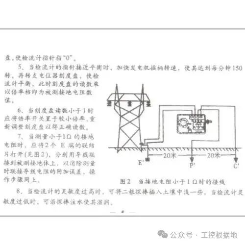
2. Ground Resistance Value Requirements
Core Standard: Must comply with TN-S grounding system, with ground resistance ≤4Ω (lightning protection grounding ≤1Ω).
- Grounding Method:
- Protective grounding: The cabinet and metal components are connected to the grounding busbar via yellow-green two-color wire (cross-sectional area ≥2.5mm²);
- Signal grounding: Analog modules and communication modules must be grounded at one end to avoid forming grounding loops.
- Practical Points: Ground terminals must have “grip pads” added to break the paint layer, ensuring contact resistance <50mΩ. A certain chemical project experienced signal drift due to poor grounding, and after rectification, control accuracy improved to ±0.5%.
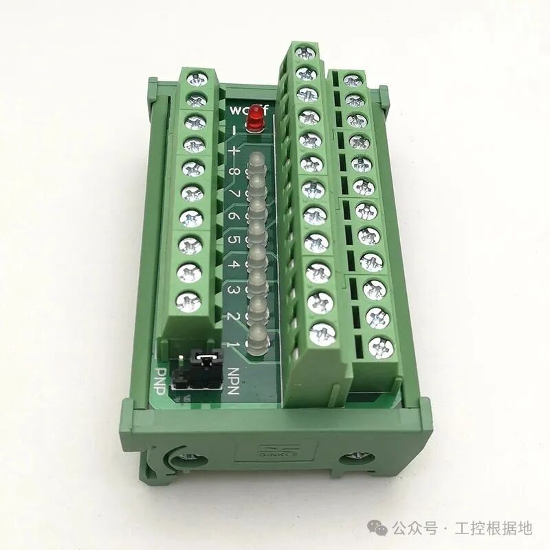
3. Input/Output (I/O) Signal Type Configuration
Classification Standard: According to signal nature, they are divided into digital (DI/DO) and analog (AI/AO), which must match the module type.
| Signal Type | Wiring Specification | Typical Application | Interference Prevention Measures |
|---|---|---|---|
| DI (Digital Input) | NPN type sensor connects to COM terminal (source type input), PNP type connects to 24V+ (sink type input) | Proximity switches, buttons | Wire cross-section ≥0.5mm², away from power lines |
| DO (Digital Output) | Relay output connects to AC 220V, transistor output connects to DC 24V (current ≤2A) | Solenoid valves, indicator lights | Inductive loads in parallel with flyback diodes (DC) or RC snubber circuits (AC) |
| AI (Analog Input) | 4-20mA current signals use twisted shielded wire, grounded at one end | Pressure transmitters, thermocouples | Shielding layer connected to PE, with a distance ≥30cm from power lines |
| AO (Analog Output) | 0-10V voltage signals should avoid long-distance transmission (≤50m) | Control valves, variable frequency drive speed settings | Use isolation modules to reduce common-mode interference |
Safety Risks: Incorrect polarity connections for DI/DO signals may burn out modules. A certain food factory suffered losses exceeding ten thousand yuan due to reversed polarity connections of sensors leading to the destruction of an 8-channel input module.
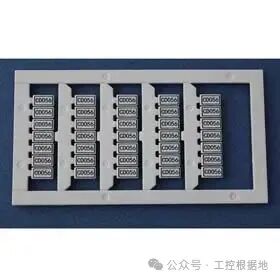
4. Terminal Block Spacing and Labeling Standards
Spacing Requirements: The spacing between adjacent terminals must be ≥Voltage Level × 0.5mm (e.g., for 220V circuits ≥3.5mm, for 380V ≥6mm), to prevent creepage short circuits.
- Labeling Standards:
- Terminal blocks must be segmented by “unit sections”, reserving ≥15% spare terminals;
- Wire ends must be labeled with circuit numbers (e.g., “DI01”, “AO03”), using B-type upright font, affixed below or to the left of the terminal.
- Case Study: A certain project experienced a creepage short circuit between the 220V control line and signal line due to insufficient terminal spacing (2.54mm), and after upgrading to 5.08mm spacing terminals, the fault was eliminated.
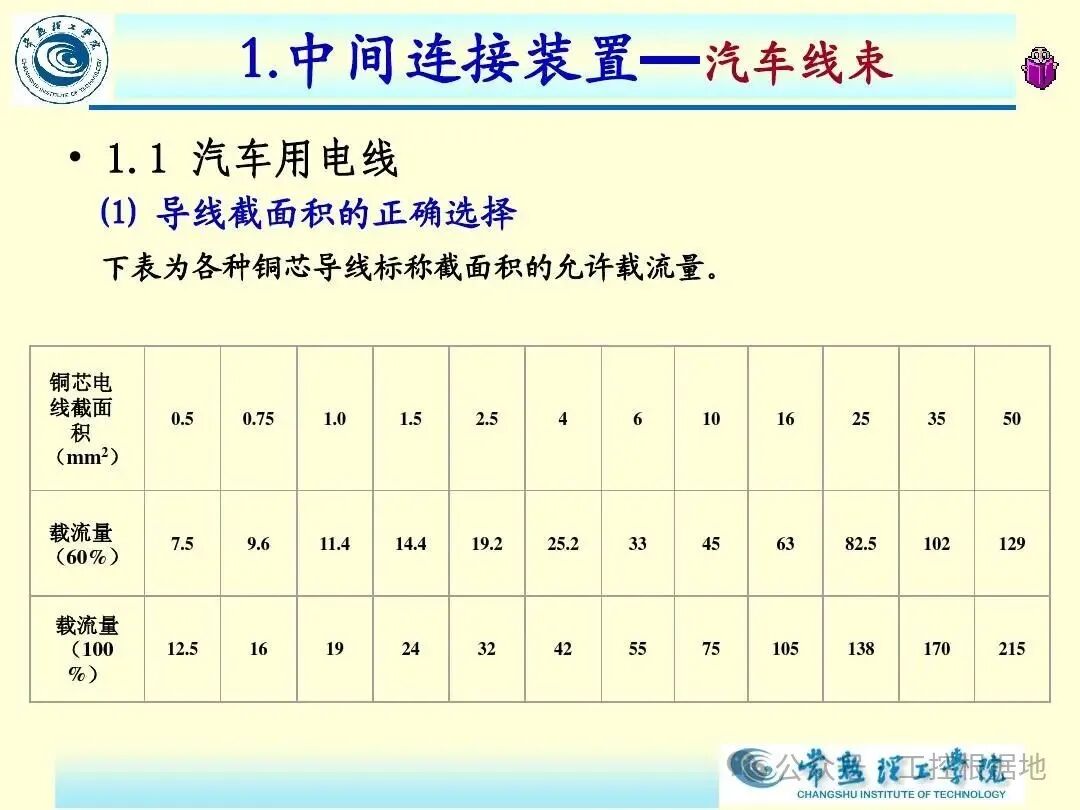
5. Wire Cross-Section Area Selection
Matching Principle: Select based on current load and installation method, meeting current-carrying capacity and mechanical strength requirements.
| Circuit Type | Wire Cross-Section Area (mm²) | Rated Current (A) | Applicable Scenarios |
|---|---|---|---|
| Control Circuit (AC/DC) | 1.5 (multi-strand copper core) | 10-16 | Buttons, indicator lights, relay coils |
| Current Circuit (CT Circuit) | 2.5 (multi-strand copper core) | 20-32 | Ammeter, power factor meter |
| Power Circuit | ≥2.5 | 25-40 | PLC power modules, switch power inputs |
| Ground Circuit | ≥2.5 (yellow-green) | – | Protective grounding, shielding layer grounding |
Taboos: Using single-strand wire instead of multi-strand wire (poor flexibility, prone to breakage); small cross-section wires carrying large currents (e.g., 1mm² wire carrying loads over 2A will overheat).
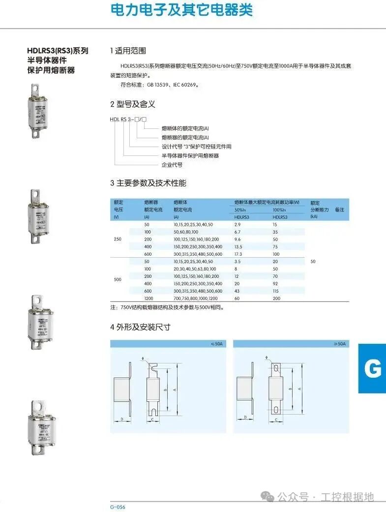
6. Fuse/Circuit Breaker Specifications
Selection Standards: Configured according to “Rated Current = 1.25 × Calculated Current“, with breaking capacity ≥ maximum short-circuit current of the circuit.
- Main Power Circuit: The main circuit breaker should be 32A/30mA leakage protection (e.g., Schneider NSX series), and branch lines should be configured with 10-16A miniature circuit breakers;
- Control Circuit: A 6.3A fast fuse (e.g., Bussmann 170M series) should be connected in series before the PLC module to prevent overcurrent damage to the CPU.
- Case Study: A certain production line suffered losses exceeding 50,000 yuan due to the lack of a fuse, which burned out the CPU during a short circuit; after rectification, a fuse was added, and during faults, only the fuse blew, reducing maintenance costs by 90%.
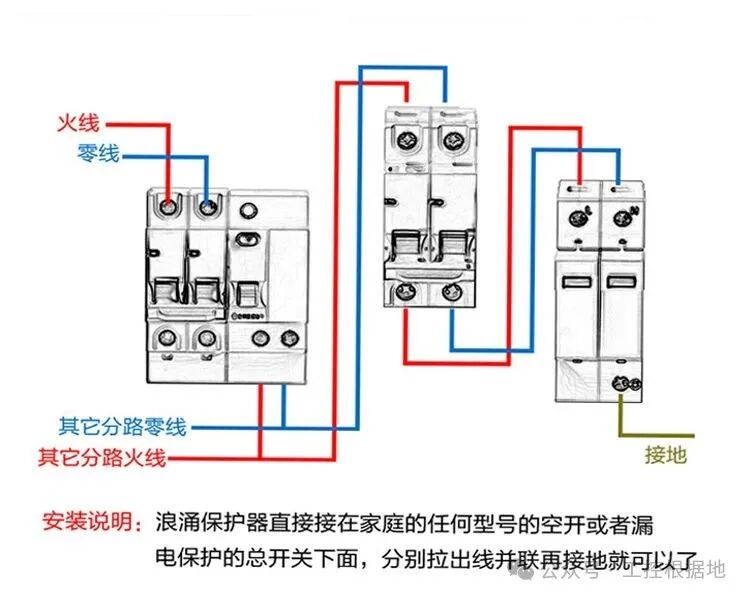
7. Surge Protective Device (SPD) Configuration
Installation Location: At the power input end (L1/L2/L3/N-PE), with a nominal discharge current In ≥20kA (8/20μs waveform).
- Parameter Requirements:
- Voltage protection level Up ≤2.5kV;
- Ground wire cross-section ≥6mm² (copper core), length ≤0.5m, avoiding sharp angle bends (bend radius ≥15 times the wire diameter).
- Industry Standards: Must comply with GB 50057, and in areas prone to lightning strikes (e.g., coastal areas), a secondary SPD (In=10kA) should be added.
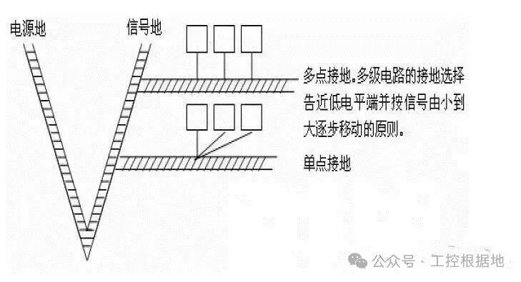
8. Shielding Layer Grounding Method
Single-End Grounding Principle: The shielding layer of signal cables should only be grounded on the control cabinet side, with the field side left floating to avoid forming “ground loops” that cause interference.
- Operational Steps:
- Strip the shielding layer for 15mm, tighten and crimp with a terminal;
- Connect to the grounding busbar using a dedicated grounding clamp (impedance ≤1Ω);
- Analog cables should have double shielding (inner shield for signal ground, outer shield for protective ground).
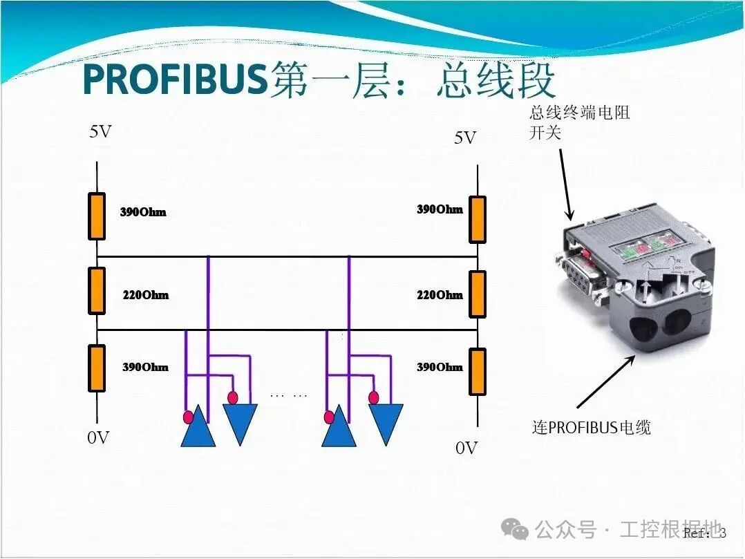
9. Communication Line Wiring Specifications
Bus Types: Communication lines such as PROFINET and Modbus must comply with IEC 61158 standards.
- PROFINET: Use CAT6A shielded twisted pair, with impedance 100Ω±20%, transmission rate ≤100Mbps at distances ≤100m;
- Modbus RTU: RS485 bus uses A/B differential signals, with 120Ω termination resistors at the ends, and a maximum of 32 nodes.
- Wiring Requirements: Communication lines must be ≥30cm away from power lines, and when crossing, they must cross perpendicularly to avoid parallel installation.
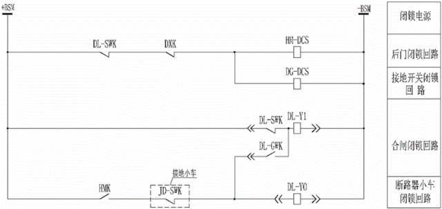
10. Safety Interlock Circuit Wiring
Design Principle: Follow the “Dual Channel Verification“, with critical interlocks (e.g., emergency stop, safety doors) independent of the PLC main program.
- Wiring Method:
- Safety relays (e.g., Schmersal SRB series) output contacts are connected in series to the control circuit;
- Interlock signals must have dual circuit inputs to the PLC, implementing “2 out of 2” logic in the software.
- Standard Basis: Comply with EN ISO 13849-1, with safety level PLd or higher.
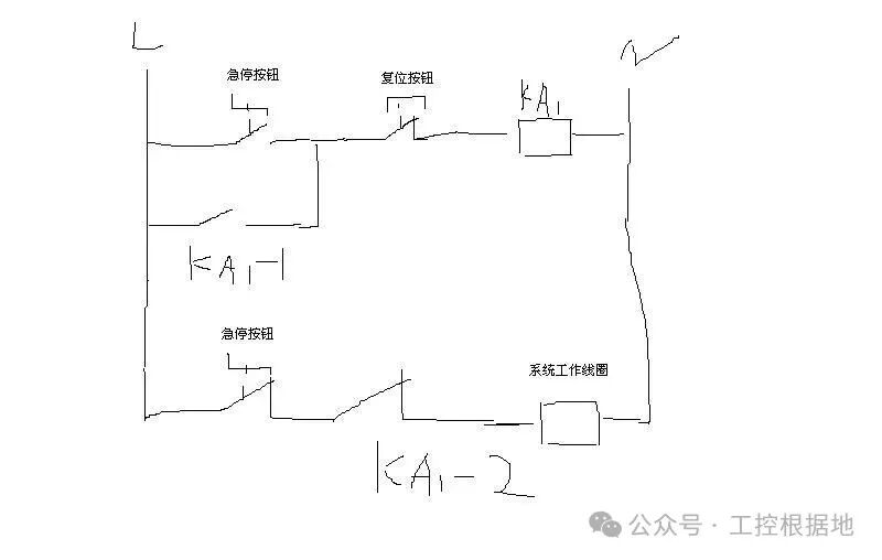
11. Emergency Stop Button Wiring
Forced Disconnection Requirement: The emergency stop button must be a normally closed contact, directly cutting off the power supply, independent of the PLC program.
- Wiring Specification:
- Use dual channel in series (e.g., two emergency stop buttons in series) to ensure single-point failure does not lead to failure;
- The button color should be red with a yellow background, installed at a height of 0.8-1.6m (in accordance with GB 50054-2011 Article 4.2.3).
- Case Study: A certain robotic arm could not stop due to the emergency stop button being connected in parallel to the PLC output; after rectification to directly cut off the contactor coil, it passed safety certification.
12. Indicator Light and Alarm Device Wiring
Color Standards: Follow GB 2682-81, with different states corresponding to fixed colors:
| State | Indicator Light Color | Alarm Type | Wiring Requirements |
|---|---|---|---|
| Normal Operation | Green | – | Connected in parallel to PLC output (current ≤100mA) |
| Fault/Alarm | Red | Audible and visual alarm | Powered by an independent source (AC 220V), isolated from the main circuit |
| Standby/Ready | Yellow | – | Series current-limiting resistor (1kΩ/0.25W) |
Installation Height: The centerline of the indicator light should be 0.6-2.0m from the ground for easy observation.
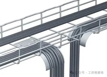
13. Cable Tray/Wire Duct Wiring Requirements
Space Reservation: The total cross-sectional area of wires in the duct should be ≤40% of the duct’s cross-sectional area, with power lines and signal lines installed in separate ducts (spacing ≥200mm).
- Fixing Method:
- Horizontal trays fixed every 1.5m, vertical trays fixed every 2m;
- Wire bundling spacing ≤300mm, wires in the same direction should be bundled together, clearly labeled.
- Protection Level: Sealed wire ducts (IP54) for dusty environments, galvanized trays with anti-corrosion treatment for humid environments.
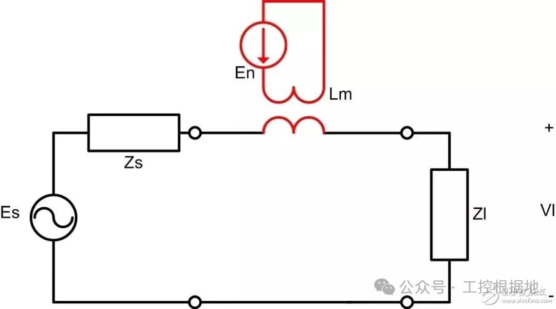
14. Interference Prevention Measures
Comprehensive Plan: Suppress interference from wiring, grounding, and isolation:
- Wiring: Analog lines should use twisted pairs + shielding, with a distance ≥50cm from variable frequency drives and motor lines;
- Isolation: Install dual-shielded isolation transformers (e.g., Schneider ABL series) on the power side, with the secondary side shield connected to PE;
- Filtering: Connect a low-pass filter (cutoff frequency 50Hz) in parallel at the PLC power input to eliminate high-frequency noise from the power grid.
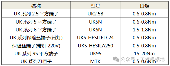
15. Terminal Tightening Torque
Specification Value: Set torque according to terminal specifications to prevent loose contacts or damage from over-tightening.
| Terminal Type | Bolt Specification | Recommended Torque (N·m) | Testing Tool |
|---|---|---|---|
| UK Series General Terminal | M3 | 0.8-1.2 | Torque wrench (with scale) |
| High Current Terminal (35mm²) | M5 | 2.5-3.0 | Torque screwdriver |
| Spring Terminal (Push-in) | – | Wire inserted fully, no looseness | Tensile test (≥5N) |
Testing Requirements: After wiring, 100% re-tightening is required, and before operation, use an infrared thermometer to check terminal temperatures (temperature rise ≤40K).
Conclusion
Wiring of PLC control cabinets must strictly adhere to the principle of “Safety First, Standard Operation“, as each configuration of the 15 parameters directly affects system reliability. In engineering practice, it is recommended to combine GB 50054-2011 and equipment manuals, ensuring compliance through a four-step process of “drawing review – wiring – testing – recording”. Regular testing of terminal tightness, ground resistance, and insulation performance can reduce system failure rates by over 70%, ensuring continuous and stable operation of industrial automation production.
(Note: The schematic diagrams in the text can refer to authoritative materials such as the “Terminal Specification Diagram” from the “Connection World Network” and the “PLC Wiring Manual” from the “Siemens Industrial Support Center”.)### 1. PLC Power Voltage Wiring Diagram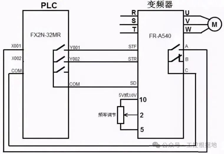
2. Ground Resistance Value Specification
3. DI/DO/AI/AO Signal Terminals
4. Terminal Block Labeling Standards
5. Wire Cross-Section Area Selection Table
6. PLC Fuse Specifications
7. Surge Protector Wiring
8. Shielding Layer Grounding Method
9. PROFINET Communication Line Wiring
10. Safety Interlock Circuit Diagram
11. Emergency Stop Button Wiring Diagram
12. PLC Indicator Light Wiring
13. Cable Tray Wiring Specifications
14. Anti-Interference Twisted Pair Connection Method
15. Terminal Tightening Torque Standards
 Like, follow, and share