“ This article focuses on the Wi-Fi architecture and TCP/IP protocol implementation of the ESP32-S3. It analyzes the core modules integrated into its 40nm chip, including the RF front end and baseband, details the STA/AP working modes, dissects the STA connection process and data path, and compares the OSI and TCP/IP protocol stack implementations.”
01
—
ESP32-S3 Chip-Level Wi-Fi Architecture
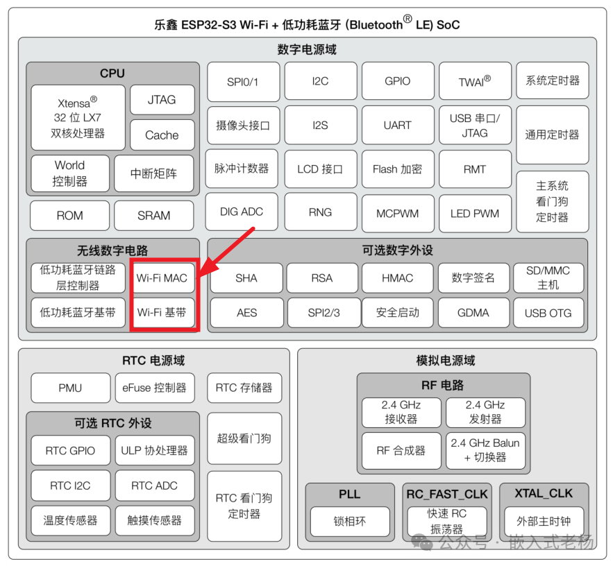
The ESP32-S3 integrates a complete 2.4 GHz Wi-Fi subsystem on a single 40 nm CMOS wafer. The functional partitions are as follows:
RF Front End:
On-chip power amplifier (+20 dBm@11b), low-noise amplifier, transceiver switch, and balun, requiring only an external 50 Ω antenna or a printed inverted F antenna.
Baseband Processor:
Hardware implementation of IEEE 802.11 b/g/n physical layer, supporting 20 MHz and 40 MHz channels, with a maximum PHY rate of 150 Mbit/s (HT40 MCS7).
Media Access Controller (MAC):
Hardware execution of DCF, EDCA, Block-ACK, A-MPDU/A-MSDU, and immediate retransmission, reducing CPU usage.
Security Engine:
Independent AES-128/256, GCMP, CCMP, TKIP accelerators, supporting WPA3-SAE, TLS1.3, WAPI, and WPS, with no CPU intervention required during the handshake process.
Network Interface:
Up to four virtual network interfaces (netif), sharing the same RF through time division multiplexing.
Resources:
Internal 64 kB TX/RX DMA circular buffer, CPU Cache can be dynamically configured; a system clock of 40 MHz crystal is sufficient. Peripherals only require antenna matching network, π-type filter, and power supply.
02
—
Wi-Fi Operating Modes
|
Mode |
Function Description |
Typical Applications |
|
STA |
Client, associates with external access point |
Sensors, gateways |
|
Soft-AP |
Ad-hoc network, up to 10 STAs can associate |
One-click network configuration, local monitoring, hotspot |
|
STA+AP |
Acts as both STA and Soft-AP |
Relay, transparent gateway |
|
Sniffer |
Only receives 802.11 frames, does not send association frames |
Protocol analysis |
|
Promiscuous |
Promiscuous listening, can capture all MAC frames |
RSSI ranging, positioning |
03
—
TCP/IP Protocol Stack
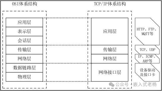
The ESP32-S3’s protocol stack is an open-source TCP/IP embedded network protocol stack implemented using the lwIP library. The TCP/IP protocol stack does not completely correspond to the traditional OSI model. The TCP/IP protocol stack is a simplified model that emphasizes the actual protocol implementations and the real operation of the Internet. In contrast, the OSI model is more comprehensive and idealized, providing a framework to describe the interactions between different systems. The following diagram compares the layered architecture of the IOS protocol stack with the TCP/IP protocol stack.
|
OSI Layer |
TCP/IP Layer |
ESP32-S3 Implementation |
Key Resources |
|
7 Application Layer |
Application Layer |
LwIP Socket + mbedTLS + User Protocol Library |
Software |
|
6 Presentation Layer |
Application Layer |
mbedTLS Encryption, Compression |
Hardware AES |
|
5 Session Layer |
Application Layer |
LwIP PCB, Sockets |
Software |
|
4 Transport Layer |
Transport Layer |
LwIP TCP/UDP |
Software |
|
3 Network Layer |
Network Layer |
LwIP IPv4/IPv6, ARP/DHCP/ICMP |
Software |
|
2 Data Link Layer |
Network Interface Layer |
Wi-Fi MAC / Ethernet MAC |
Hardware |
|
1 Physical Layer |
Network Interface Layer |
2.4 GHz PHY / RMII PHY |
Hardware + Antenna |
04
—
STA Mode Configuration Process
Enable Process::
-
Initialization: esp_netif_init() → esp_event_loop_create_default() → esp_wifi_init().
-
Set Mode: esp_wifi_set_mode(WIFI_MODE_STA).
-
Configure Parameters: Fill in SSID, password, channel, and encryption method in the wifi_config_t structure.
-
Start RF: esp_wifi_start().
-
Trigger Connection: esp_wifi_connect().
-
Event Feedback: The kernel delivers WIFI_EVENT_STA_CONNECTED and IP_EVENT_STA_GOT_IP in the default event loop.
Connection Mechanism::
-
Probe Phase: STA sends Probe Request in the 2.4 GHz band, AP replies with Probe Response.
-
Authentication Phase: Uses Open System or SAE/WPA2-PSK four-way handshake.
-
Association Phase: Association Request/Response exchange, establishing AID.
-
DHCP Phase: Obtains IPv4 address via DHCP (or static IP).
Data Path::
-
TX: Application layer data → LwIP TCP/IP → MAC layer → Baseband modulation → RF transmission.
-
RX: RF demodulation → Baseband → MAC filtering → LwIP → Socket.
-
Modem-sleep: DTIM cycle wake-up, average current 15–20 mA.
-
Light-sleep: CPU and RF short power-off, average current 2–5 mA.
-
Deep-sleep: Only RTC runs, current <10 µA, can be awakened by timer or GPIO.
05
—
Program Design
1.Global Initialization
-
Before any Wi-Fi action, three things must be completed:
-
nvs_flash_init()—Open non-volatile storage to save Wi-Fi calibration data and last connection configuration;
-
esp_netif_init()—Create LwIP virtual network card framework, laying the foundation for subsequent IP, DHCP, DNS;
-
esp_event_loop_create_default()—Establish system event post office, where Wi-Fi driver will deliver WIFI_EVENT and IP_EVENT.
2.Create STA Network Card Instance
Call <span>esp_netif_create_default_wifi_sta()</span> to return an <span>esp_netif_t *</span> handle, on which all subsequent IP layer operations (DHCP, DNS, static address) will depend. This function internally binds the network card to the Wi-Fi driver, requiring no additional setup.
3.Initialize Wi-Fi Driver
wifi_init_config_t cfg = WIFI_INIT_CONFIG_DEFAULT();esp_wifi_init(&cfg);Load the internal Wi-Fi firmware into RAM and start a driver task with priority 23 and stack size of 6 kB. The cfg contains default values such as country code and DMA buffer size, which can be directly generated using macros.
4.Set Working Mode
esp<span>_wifi_set_mode(WIFI_MODE_STA)</span> fixes the RF to the “station” role. Other optional values include <span>WIFI_MODE_AP</span>, <span>WIFI_MODE_APSTA</span>, <span>WIFI_MODE_NULL</span>, and once set, all subsequent configurations must follow the structure type corresponding to that role.
5.Fill in Connection Parameters
wifi_config_t wifi_config = { .sta = { .ssid = "YOUR_SSID", .password = "YOUR_PASSWORD", .scan_method = WIFI_ALL_CHANNEL_SCAN, .sort_method = WIFI_CONNECT_AP_BY_SIGNAL, .threshold = { .rssi = -127 }, },};esp_wifi_set_config(WIFI_IF_STA, &wifi_config);SSID and password can be up to 32 bytes; other fields filled with 0 indicate automatic selection of channel and security policy. To force connection to a specified MAC, additionally set .bssid_set = 1 and fill in .bssid[6].
6.Start RF and Trigger Connection
First <span>esp_wifi_start()</span> opens the RF, then <span>esp_wifi_connect()</span> initiates the 802.11 association and four-way handshake. These two steps can be executed consecutively; if you want to scan first and then connect, you can place <span>esp_wifi_connect()</span> after <span>esp_wifi_scan_start()</span><span><span>.</span></span>
7.Wait for Events and Obtain IP
Register in the event loop
esp_event_handler_register(WIFI_EVENT, ESP_EVENT_ANY_ID, event_handler, NULL);esp_event_handler_register(IP_EVENT, IP_EVENT_STA_GOT_IP, event_handler, NULL); Wi-Fi Configuration Program:
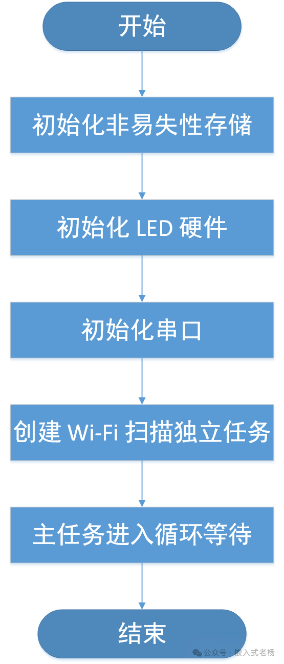
static void wifi_scan_task(void *pvParameters){ /* 1. Initialize network interface layer */ ESP_ERROR_CHECK(esp_netif_init()); /* 2. Create default event loop (for Wi-Fi driver to deliver events) */ ESP_ERROR_CHECK(esp_event_loop_create_default()); /* 3. Create default STA network card */ esp_netif_create_default_wifi_sta(); /* 4. Initialize Wi-Fi driver */ wifi_init_config_t cfg = WIFI_INIT_CONFIG_DEFAULT(); ESP_ERROR_CHECK(esp_wifi_init(&cfg)); /* 5. Set to STA mode */ ESP_ERROR_CHECK(esp_wifi_set_mode(WIFI_MODE_STA)); /* 6. Start RF */ ESP_ERROR_CHECK(esp_wifi_start()); /* 7. Scan parameters: NULL means default full channel scan, true means blocking until complete */ ESP_ERROR_CHECK(esp_wifi_scan_start(NULL, true)); /* 8. Get results */ uint16_t number = DEFAULT_SCAN_LIST_SIZE; wifi_ap_record_t ap_info[DEFAULT_SCAN_LIST_SIZE]; uint16_t ap_count = 0; memset(ap_info, 0, sizeof(ap_info)); ESP_ERROR_CHECK(esp_wifi_scan_get_ap_records(&number, ap_info)); ESP_ERROR_CHECK(esp_wifi_scan_get_ap_num(&ap_count)); ESP_LOGI(TAG, "Total APs scanned = %u", ap_count); for (int i = 0; i < number && i < ap_count; i++) { ESP_LOGI(TAG, "SSID %s", ap_info[i].ssid); ESP_LOGI(TAG, "RSSI %d", ap_info[i].rssi); print_auth_mode(ap_info[i].authmode); if (ap_info[i].authmode != WIFI_AUTH_WEP) { print_cipher_type(ap_info[i].pairwise_cipher, ap_info[i].group_cipher); } ESP_LOGI(TAG, "Channel %d\n", ap_info[i].primary); } /* Task ends, delete itself */ vTaskDelete(NULL);}Main Program Flowchart:
This article’s case uses the following hardware and software:
1. SOC Model: ESP32-S3-N16R8;
2. Software Development Environment: ESP-IDF 5.3.1, VSCode IDE (VSCodeUserSetup-x64-1.102.1 version);
3. ESP32 Project Version: IDF version (FreeRTOS);
4. Program Download: Type C USB (USB to Serial) interface;
5. The hardware and software case in this article is for personal learning only and not for commercial use.
References for this article:
“ESP32-S3 Technical Reference Manual Version 1.7”;
“ESP32-S3 Series Chip Technical Specification Version 2.0”.