1. Concept Introduction
1.1 What is the Boot Process of a Microcontroller?
The boot process of a microcontroller refers to a series of initialization steps that occur from the moment power is applied or the device is reset until the user code begins execution. Different microcontrollers have specific details in their boot processes, but most follow a common pattern.
General Boot Process:
1. Power On or Reset: The boot process begins when the microcontroller is powered on or reset. Resetting can be triggered by software or through a hardware reset pin.
2. Execute Built-in Boot Code: The microcontroller first executes firmware stored in internal ROM, which is typically pre-programmed by the manufacturer. This code is unchangeable and is referred to as the bootloader.
3. Hardware Initialization: The bootloader performs hardware initialization, including setting up the clock (e.g., crystal oscillator or internal RC oscillator), configuring power management, and initializing the memory controller.
4. Check Boot Mode: The microcontroller may check certain pins or configuration registers to determine the boot mode, such as whether to enter programming mode, normal boot, or other special modes.
5. Load User Program: In normal boot mode, the bootloader loads the initial code of the user program from a preset memory location (usually built-in or external non-volatile memory like Flash) into RAM.
6. Jump to Main Program: Once the user program is loaded, control is transferred to the entry point of the user program, typically the main() function. At this point, the user program begins execution.
7. User Program Execution: The user program executes initialization code as designed, such as setting up peripherals, initializing variables, and configuring interrupt service routines, before entering the main loop or starting task scheduling (if an operating system is used).
2. Overview of the ESP32 Boot Process
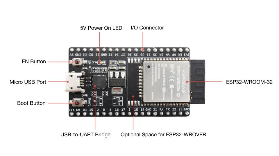
ESP32-DevKitC Development Board:
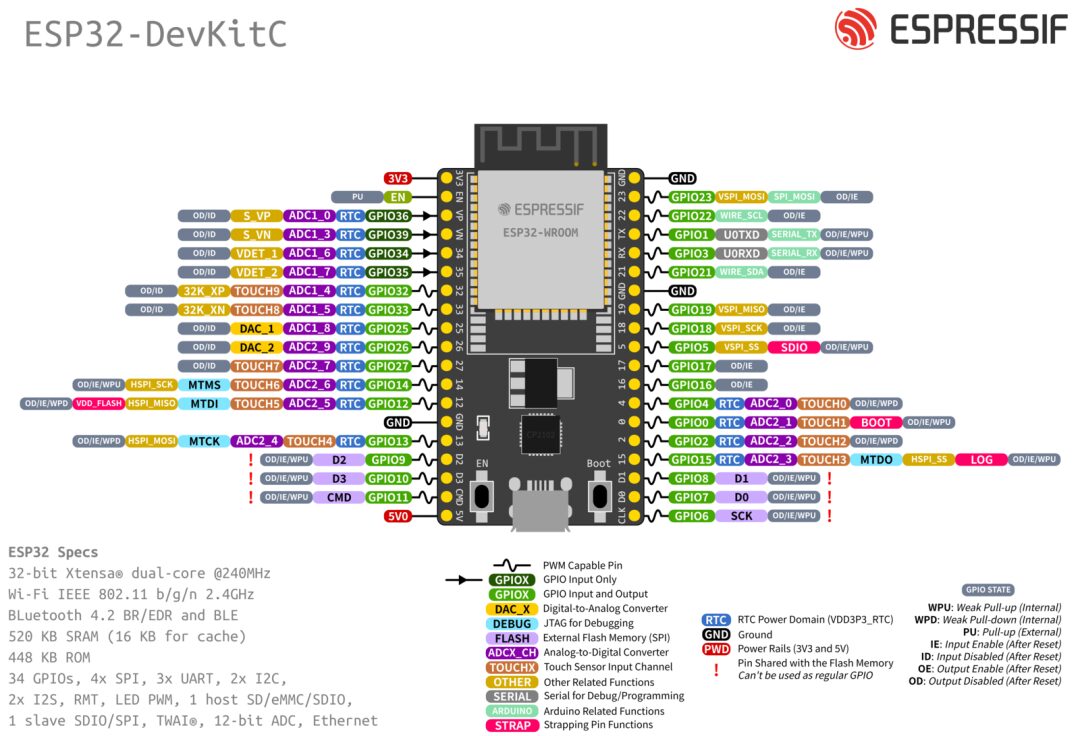
ESP32-DevKitC Pinout:
ESP32 Functional Block Diagram

Broadly, the boot process can be divided into the following 3 steps:
2.1 First Stage Bootloader
Storage Location: The first stage bootloader is burned into the internal read-only memory (ROM) of the ESP32, making it unchangeable.
Main Responsibilities: Initializes hardware, such as configuring the clock system, power management, and memory.
Boot Process After Powering On or Resetting the ESP32
1. First, the PRO CPU is activated: (The ESP32 is a dual-core microcontroller, consisting of PRO CPU (usually the main CPU) and APP CPU) After a reset, the PRO CPU is activated first and begins executing the reset vector code located in the ESP32 chip’s mask ROM (the reset vector code is the first code executed after a reset event occurs) at address 0x40000400, which is unmodifiable. The APP CPU remains in a reset state during this stage and does not participate in the initialization process.
2. Execute Reset Vector Code: The reset vector code first checks the value of the GPIO_STRAP_REG register, which records the status of different pins during reset to determine the operating mode of the ESP32.
3. Determine Operating Mode: When waking up from deep sleep mode, the system checks the values of the RTC_CNTL_STORE6_REG and RTC_CNTL_STORE7_REG registers. If the value of RTC_CNTL_STORE6_REG is non-zero and the CRC check of RTC_CNTL_STORE7_REG is valid, it jumps to the address specified by RTC_CNTL_STORE6_REG to execute code. If the check is invalid or RTC_CNTL_STORE6_REG is zero, or if the code at the specified address finishes execution and returns, it performs power-on reset related operations.
4. Power-On Reset, Software SoC Reset, Watchdog SoC Reset: The system checks for download mode requests from UART or SDIO. If there are any, it configures the UART or SDIO interface to wait for code download. If not, it continues with software CPU reset related operations.
5. Load and Execute Code: For software CPU resets and watchdog CPU resets, the system configures SPI Flash and attempts to load code from Flash into execution memory. If loading fails, it decompresses the BASIC interpreter into RAM and attempts to start it.
Note that the RTC watchdog may still be enabled at this point. If no input events occur within the set time, the watchdog will reset the SoC, restarting the entire process.
If input is received via UART, the program will disable the watchdog timer.
6. APP CPU Startup:
In the call_start_cpu0 function, the reset state of the APP CPU is released, and it begins executing the program, joining the system’s task processing.
2.2 Second Stage Bootloader
The binary image of the second stage bootloader is loaded from the flash at offset 0x1000. If secure boot is in use, the first 4 kB sector of flash is used to store the secure boot IV and the digest of the bootloader image; otherwise, this sector is not used.
Detailed Explanation
1. Function and Location of the Second Stage Bootloader
Storage Location: The binary image of the second stage bootloader is stored at offset 0x1000 in flash memory.
Source Code Location: The source code is located in the ESP-IDF components/bootloader directory, allowing developers to view and modify the source code to suit specific application needs.
Increased Flexibility: The second stage bootloader makes the use of the flash partition table flexible, aiding in the configuration and management of system resources.
Security Features: It provides the implementation foundation for advanced features such as flash encryption, secure boot, and over-the-air (OTA) upgrades.
2. Boot Process
Loading Process: The first stage bootloader is responsible for verifying and loading the second stage bootloader into RAM. It finds the entry point from the header of the binary image and then jumps to that address to start executing the second stage bootloader.
Read Partition Table: The second stage bootloader by default reads the partition table from offset 0x8000, which is configurable. The partition table contains information on how to organize different data (such as applications, file systems, etc.) in flash.
Partition Table and OTA: The bootloader looks for the factory partition and OTA application partition. If it finds an OTA application partition, it checks the otadata partition to decide which partition should be started. (OTA updates refer to the process of installing or upgrading the operating system or applications directly on the device over the network, such as Wi-Fi or cellular networks.)
Configuration Options: ESP-IDF provides a rich set of configuration options that allow us to adjust the behavior of the bootloader as needed.
3. Read and Map Program Segments
Internal RAM Segments: For segments that need to be loaded into internal IRAM or DRAM, the second stage bootloader copies data from flash to the corresponding load address.
DROM/IROM Segments: For segments with load addresses in the DROM or IROM areas, the second stage bootloader configures the flash MMU mapping for direct execution from flash.
Flash MMU Configuration: The second stage bootloader configures the flash MMU for both PRO CPU and APP CPU, but only enables the MMU for the PRO CPU. The MMU for the APP CPU will be left for the application to handle, as the second stage bootloader has already been loaded into the memory area that the APP CPU will use.
4. Application Loading and Execution
Integrity Check: After all segments have been processed, the second stage bootloader verifies the integrity of the application to ensure that the code has not been tampered with.
Jump to Execute: It finds the entry address of the application from the header of the binary image and jumps to that address to officially start executing the user’s application.
2.3 Application Startup Phase
The application startup includes all processes from the start of the application execution to the running of the app_main function in the main task. It can be divided into three stages:
1. Port initialization of hardware and basic C language runtime environment.
2. System initialization of software services and FreeRTOS.
3. Run the main task and call app_main.
Detailed Explanation
Port Initialization
The entry point of an ESP-IDF application is the call_start_cpu0 function in the components/esp_system/port/cpu_start.c file. This function is executed by the second stage bootloader and never returns.
call_start_cpu0 Function
Location: in components/esp_system/port/cpu_start.c.
Function: Serves as the entry point for ESP-IDF applications, called by the second stage bootloader to start the PRO CPU (the first CPU core).
Characteristics: This function performs a series of initialization tasks and never returns, as it will ultimately jump to the main function of the application.
The initialization functionality of this port layer initializes the basic C runtime environment (“CRT”) and performs initial configurations of the SoC’s internal hardware.
Initialization Functions
1. C Runtime Environment Initialization:
Sets up the basic C runtime environment, such as initializing the stack, data segments, BSS segments, etc.
This provides the necessary environment for the execution of C language program code.
2. SoC Hardware Configuration:
Performs initial settings for the internal hardware of the ESP32 chip, including clocks, GPIO, interrupts, etc.
3. CPU Exception Configuration:
Reconfigures the CPU exception handler, allowing the application to handle interrupts and serious errors independently, rather than relying on the basic error handler in ROM.
4. RTC Watchdog Timer:
If CONFIG_BOOTLOADER_WDT_ENABLE configuration is not enabled, the RTC watchdog will not be enabled.
The watchdog timer is used to monitor the system’s operational state, preventing the system from hanging.
5. Memory Initialization:
Initializes internal memory, clearing the data segment and uninitialized data segment (BSS).
6. MMU and Cache Configuration:
Completes the setup of the memory management unit (MMU) and configures the cache behavior of the CPU.
7. PSRAM Configuration:
If external PSRAM (Pseudo-static RAM) is configured, it will be initialized and enabled.
8. CPU Clock Configuration:
Sets the clock frequency at which the CPU operates according to project configuration.
9. Main SPI Flash Configuration:
Reconfigures the main SPI Flash based on the application header settings to ensure compatibility with bootloaders prior to ESP-IDF V4.0.
10. Start Other Cores:
If the application is configured to run on multiple cores, the APP CPU is started, and similar initialization is completed in the call_start_cpu1 function.
System Layer Initialization
The main system initialization function is start_cpu0. By default, this function is weakly linked with the start_cpu0_default function. This means that this function can be overridden to add some additional initialization steps.
start_cpu0 Function:
After call_start_cpu0 completes, the next function called is start_cpu0 in the startup.c file.
This function continues with system-level initialization, such as starting FreeRTOS and initializing system services and daemons.
start_other_cores Function:
For multi-core configurations, each core, after completing port layer initialization, will call the start_other_cores function to ensure that all cores synchronize to complete system layer initialization.
The main phases of system initialization include:
1. Log Application Information:
If the log level set by the system allows, the initialization phase will log important information about the application, such as project name and version. This is very useful for debugging and problem tracing, as it quickly informs developers or maintainers of the current running program’s details.
2. Initialize Heap Allocator:
Before this stage, all memory allocations need to be static, meaning they must be determined at compile time or allocated on the stack as temporary local variables. After the heap allocator is initialized, the program can dynamically allocate memory on the heap, which is necessary for most runtime memory management tasks.
3. Initialize Newlib Components:
Newlib is a C standard library implementation designed for embedded systems. At this stage, system calls (syscalls) and time functions are initialized, allowing applications to use standard C library functions such as file operations and time retrieval.
4. Configure Power Failure Detector:
This ensures that the system can detect and take appropriate measures in case of insufficient power, possibly by saving state or shutting down gracefully to avoid data corruption or inconsistency.
5. Set Standard Input and Output for libc:
Standard input and output (stdin, stdout, stderr) are configured to communicate through the serial console, which is crucial for outputting real-time debugging information and error message reporting.
6. Execute Security-Related Checks:
At this stage, the system performs a series of security checks, including burning efuses, which are one-time writable memories used to store encryption keys or configuration options. For example, this may include disabling the ROM download mode of ESP32 V3, preventing reprogramming of the device through a simple console of the ROM bootloader, thus enhancing security.
7. Initialize SPI Flash API Support:
SPI flash is a commonly used storage medium for ESP32 devices. Initializing SPI flash API support means that the software interface for interacting with the storage device is set up, allowing applications to read and write flash.
8. Call Global C++ Constructors and C Functions with Special Attributes:
In C++, global objects need to be constructed before the main function executes. This stage ensures that the constructors of all global objects are called. For C, any functions marked with the __attribute__((constructor)) attribute will also be executed at this time. These functions are typically used for initialization tasks.
9. Secondary System Initialization:
At this stage, the system allows individual components to initialize. If a component declares an initialization function annotated with the ESP_SYSTEM_INIT_FN macro, it will be called here. This allows for finer-grained control, and components can independently perform any required startup configurations.
Run Main Task
After all other components are initialized, the main task is created, and the FreeRTOS scheduler begins running.
After completing the initialization of all other components, the system creates a main task and starts the FreeRTOS task scheduler. Subsequently, this main task executes the app_main function provided by the programmer within the firmware.
When executing app_main, the main task will have a predetermined RTOS priority that is higher than the lowest possible setting, and its stack size can be configured as needed. Additionally, the main task’s affinity can be set to run on a specific CPU core through CONFIG_ESP_MAIN_TASK_AFFINITY.
Unlike a typical FreeRTOS task or the main function in an embedded C program, the app_main function can choose to return after execution. Once app_main returns, the main task will end and be removed from the system, but FreeRTOS will continue to run other tasks in the system. This allows app_main to be designed to either simply start other tasks and then exit or run continuously as the main application task.
Explaining some of the terms mentioned above:
1. Create Main Task:
In FreeRTOS, all code runs in tasks. After the initialization process is complete, the system creates a new task to run the app_main function.
2. Start RTOS Scheduler:
The FreeRTOS scheduler is the core component responsible for task management. It determines which task should run when. After the main task is created, the scheduler begins running, managing app_main and other tasks in the system.
3. Run app_main Function:
app_main is the user-defined entry point that executes in the main task, completing application-specific initialization tasks. This may include setting up hardware peripherals, initializing global resources, creating additional tasks, etc.
4. Attributes of the Main Task:
While running app_main, the main task has a fixed RTOS priority that is higher than FreeRTOS’s minimum priority. This ensures that app_main can execute relatively quickly during system startup.
The stack size of the main task is configurable to ensure there is enough memory space to execute the code in app_main.
Using the CONFIG_ESP_MAIN_TASK_AFFINITY configuration option, the affinity of the main task can be set to determine which CPU core it should run on, which is important for multi-core processors.
5. Lifecycle of the Task:
Unlike a regular FreeRTOS task, app_main can return after execution instead of looping indefinitely. When app_main returns, the main task will be deleted.
Even if the main task is deleted, the FreeRTOS scheduler will continue running, scheduling any other tasks that may have been created.
6. Continuous Operation of the System:
app_main can be implemented to only initialize and create other tasks before returning. In this case, the main application logic will execute in other tasks created by app_main.
If app_main returns, FreeRTOS and ESP-IDF will ensure that the system continues running other tasks. This allows app_main to be flexibly designed as either the main application task or an initialization routine that starts other tasks.