After more than ten days of crazy shopping, assembling, debugging, disassembling, reassembling, and debugging again, my WiFi Robot is finally here!! Tears of joy! Below is a brief account of the production process, just to keep a record for myself.
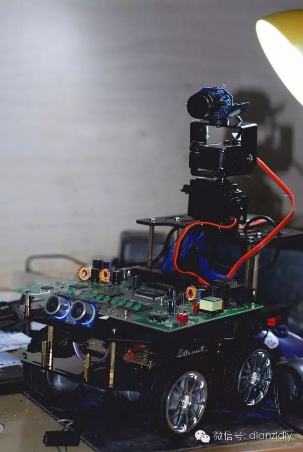
The solution I used is the WiFi car scheme from the igee forum, with a ready-made driver board and control program… However, I now realize that while using ready-made components is convenient, the expansion capabilities are quite limited. My next step is to buy an Arduino board to research and reassemble the car, and write my own programs.
The WiFi Robot, as the name suggests, is a robot controlled via WiFi. Compared to ordinary remote-controlled cars, its advantage is that the remote control signal can cover a wide range, and it can also be controlled remotely over the Internet, which opens up many new applications, such as video surveillance, etc. As a beginner, the robot’s appearance and functionality are still quite rough, so please don’t laugh at it, experts!
1. Preparation
Here is a list of parts:
Acrylic chassis ×1: 65 yuan
igee car driver board with 5110 screen ×1: 150 yuan
Ultrasonic sensor ×1: 40 yuan
DB120-B1 wireless router ×1: 45 yuan
301 chip camera ×5: The first one I bought for 10 yuan broke when I pulled the wire and couldn’t solder it, so it was discarded. The second one I bought for 10 yuan also broke… The third time I bought three, each for 5 yuan. They are all working fine now. Total: 35 yuan.
Wide-angle lens ×1: 5.3 yuan
Huisong M995 servo ×2: 70 yuan
Servo gimbal bracket ×1: 32 yuan
Stepper motor kit ×4: 144 yuan
12V 4800mAh lithium battery: 87 yuan
Dupont wires, screws, nuts, and other miscellaneous parts…
Total: 673.3 yuan
Since this is my first time making a robot, I had no tools, and just buying a soldering iron, hot glue gun, electric drill, and multimeter cost quite a bit. Including various other expenses, the total was over 1200 yuan. I spent more than a month’s living expenses…
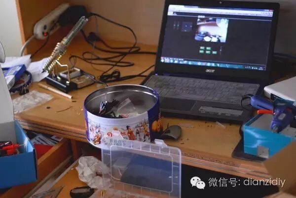
Everyone, take a look at my working environment.
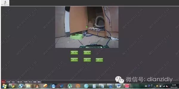
The dormitory conditions are quite simple… The computer screen shows the robot control interface.
Before I bought the acrylic chassis and electric drill, my car was using a cardboard box as a chassis. Although cardboard is easy to work with, it is too soft, and the car often veers off course. Additionally, due to the improper wheelbase, after adding the servo gimbal, the increased weight caused too much resistance for turning, making the car almost unable to turn.
I forgot to take a picture before disassembly, so I can only piece together a photo after disassembly. You can still vaguely see the original shape of the car.
Acrylic sheets are very cheap and easy to process, and you can easily make your own instead of buying finished sheets. However, the downside is that they are not as sturdy and eye-catching as aluminum sheets, and cracks can occur when screwing in. If you choose aluminum for the chassis, you might consider using aluminum boxes or angle aluminum, which can also make a very good chassis with simple processing.
3. Official Start!
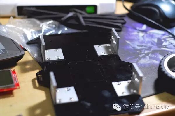
First, install the motor brackets on the chassis. Drill holes in suitable places and install the motor brackets. Be careful not to make the hole diameter too small, as forcing screws can cause the acrylic to crack. Also, when drilling, use a center punch to avoid misalignment.
If you are making a custom chassis, you need to consider the wheelbase. I made a four-wheel drive car, and turning left or right relies on reversing the wheels on either side, so a wide wheelbase can easily cause too much turning resistance.
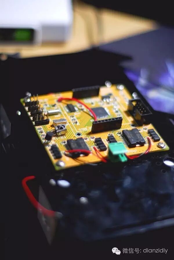
Secure the driver board at the front. You might consider using copper pillars to elevate the board for easier wire routing.
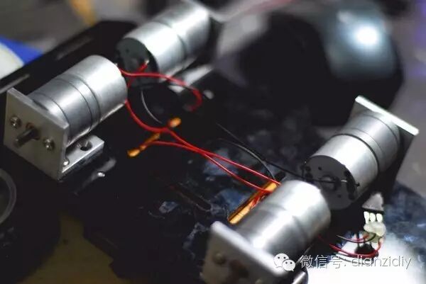
Install the stepper motors and solder the control wires. Before soldering, apply some flux to the wire ends to make soldering easier. Additionally, the servo power supply part of this driver board uses an L7805 ($0.1250), which generates a lot of heat during operation. I fixed it to the aluminum motor bracket with screws to help dissipate heat; using a metal chassis would improve the effect even more.
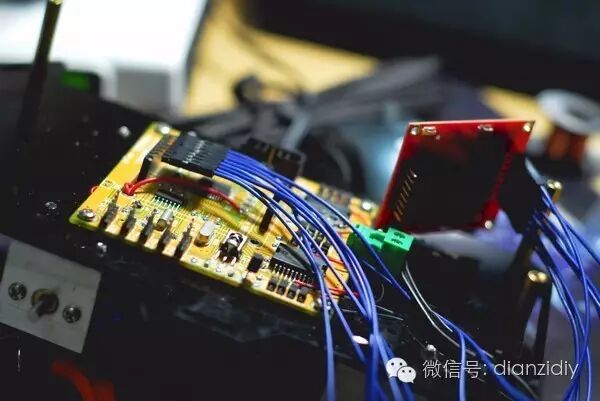
The 5110 screen was originally fixed to the board. To make it easier to view, I used Dupont wires to extend it.
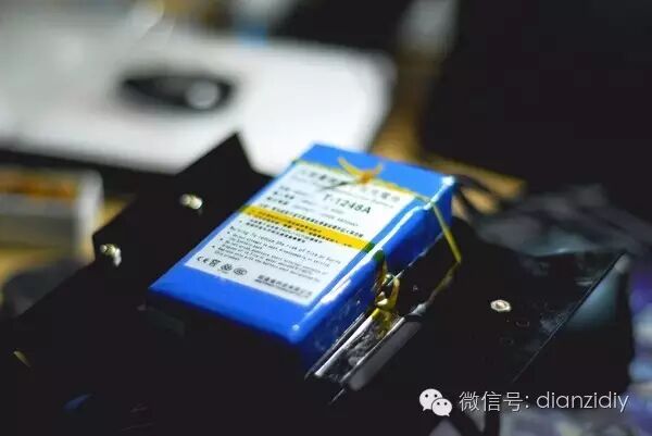
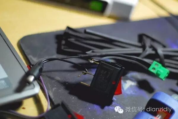
On the back of the second layer of the chassis, I fixed the battery. I originally wanted to make a drawer for easy removal, but I couldn’t find suitable materials, so I ended up using tape and rubber bands to secure it, and installed a boat switch on the side of the chassis to control the power to the driver board.
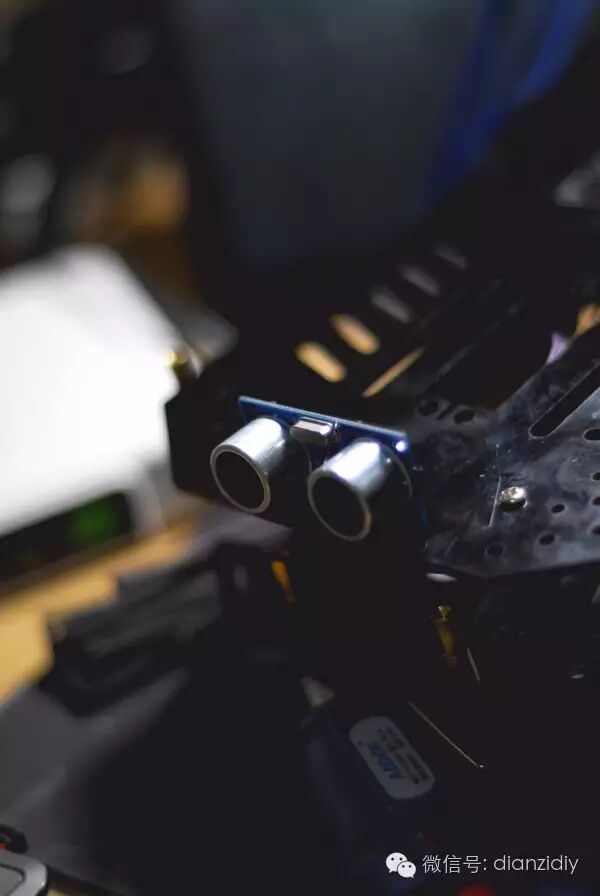
At the front of the car, I installed the ultrasonic sensor. I used hot glue to secure it, but the effect is not very good, so I plan to modify it. Be careful not to let it extend out of the chassis to avoid damage when the car hits a wall.
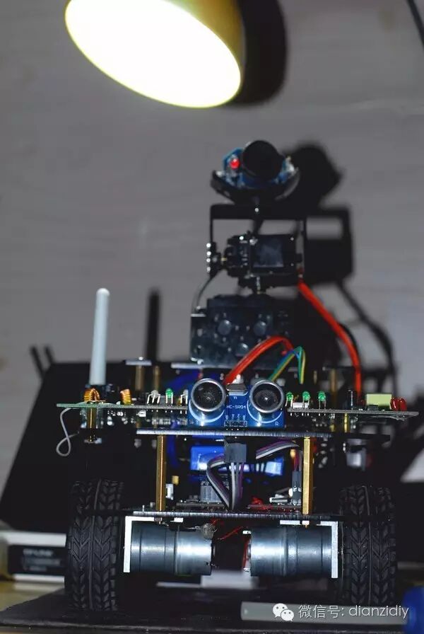
On the second layer of the chassis, I installed the router circuit board. The DB120 router is actually a telecom-customized router modem with ADSL functionality, so it is relatively large and exceeds the width of the chassis. Unfortunately, I had to drill two holes in the areas of the circuit board without wiring and secure it to the chassis with copper pillars. After installation, I found that a row of indicator lights on the router can serve as the car’s headlights, which is quite nice.
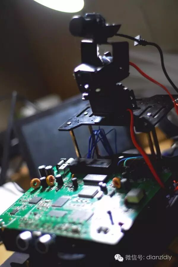
On the third layer of the chassis, I installed a 2-degree-of-freedom camera gimbal. The downside of this installation is obvious: heavy components like the servo and battery are concentrated at the rear of the car, making it prone to tipping over. However, due to space constraints and wire length, it is not easy to install the camera elsewhere, so I had to add weight at the front of the car to balance the center of gravity.
I used a camera housing that was too ugly, so I left the circuit board exposed. This means I had to secure the USB cable with hot glue to prevent it from being pulled out when the camera turns.
I fixed the 5110 screen to the chassis for easy viewing of operational information. The current program can display temperature and the distance to obstacles in front.
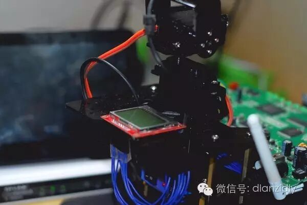
Plug the camera into the USB port of the router, connect the servo control wires to the driver board, and connect the TTL line between the router and the driver board. The car is taking shape.
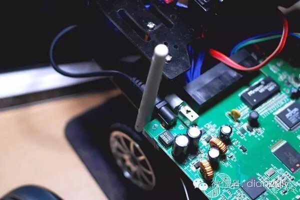
Secure the router antenna. The antenna that comes with the DB120 is too small, and I doubt the signal will be good. My next step is to buy a radar-type directional antenna to install, which would look cooler, haha. However, it seems that remote-controlled devices like this car are not suitable for directional antennas, so for now, I can only dream about it.
4. Completed!!
The car is assembled!! It looks quite nice, haha.
From this angle, it looks somewhat like a “robot”.
Next, I will flash the router with OpenWRT and install the WiFi Robot program, setting it to client mode to connect to the primary router for control. There are detailed tutorials on this part on the igee forum, so I won’t elaborate further.
This is the control interface of the car~
Since there was no need for programming or circuit design work, this car was relatively quick to make, taking about a week in total, including waiting for deliveries.
In fact, the main purpose of this car is just to play with my cat, but the real joy of creating a cool-looking WiFi robot with my own hands is what truly makes it cool, isn’t it?
Long press the QR code to follow
 Let’s walk together on the road of electronics!