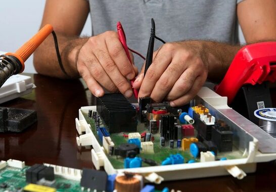
In high-speed digital signal processing (DSP) systems, electromagnetic interference (EMI) is a critical issue that cannot be overlooked. Due to the high-frequency signal processing and complex circuit layouts involved in DSP systems, the electromagnetic environment becomes more complicated, easily leading to signal distortion, system instability, and even functional failure. Therefore, engineers need to understand the electromagnetic interference issues in DSP systems.

1. Clock Circuit Harmonic Interference
The clock circuit in a DSP system is a major source of broadband noise, capable of generating harmonic distortion signals up to several hundred MHz. These high-frequency harmonics not only interfere with other circuits within the system but can also radiate externally through power lines and interconnecting cables, affecting the stability and performance of the entire system.
2. Conducted Interference and Decoupling
Conducted interference propagates through conductors, such as power lines and signal lines. In DSP systems, special attention must be paid to avoid these lines picking up noise. For example, power lines should be decoupled before entering the DSP circuit to prevent noise from the power source or other circuits from interfering with the normal operation of the system.
3. Common Impedance Coupling
The issue of common impedance coupling is particularly prominent in DSP systems. When two circuits share a common impedance, the current variation in one circuit can affect the voltage in the other circuit, leading to signal interference. To mitigate this problem, measures should be taken to reduce the impact of common impedance, such as using independent ground lines or optimizing circuit design.
4. Radiated Coupling and Crosstalk
Radiated coupling, also known as crosstalk, is caused by the electromagnetic field generated when current flows through a conductor. In DSP systems, high-frequency signals and rapidly changing circuit states can easily trigger strong electromagnetic radiation, which in turn interferes with adjacent circuits or systems. The key to reducing radiated coupling lies in optimizing PCB layout, employing shielding measures, and controlling the length and routing of signal lines.
5. Differential and Common Mode Radiation
The radiation phenomena in DSP systems can be divided into differential (DM) and common mode (CM) modes. Common mode radiation is usually more severe, potentially caused by unintended voltage drops in the circuit, leading to a rise in the potential of the entire system ground. To minimize common mode radiation, appropriate design strategies should be employed, such as adding common mode filters and optimizing ground line layouts to suppress the generation and propagation of common mode currents.
This article is an original piece by Fan Yi Education. Please indicate the source when reprinting!