Introduction
EcuBus-Pro is an open-source project designed to provide communication protocols and tools for automotive electronic control units (ECUs), enabling developers to interact with vehicle ECUs for diagnostics, debugging, data logging, and performance optimization.

It has the following main features:
-
Open-source and free
-
User-friendly interface
-
Cross-platform support (Windows, Linux, MacOS)
-
Multi-hardware compatibility, including PEAK, KVASER, ZLG, Toomoss
- Comprehensive diagnostic functions (protocol support for CAN/CAN-FD/LIN/DoIP, script automation, testing framework, database support)
EcuBus-Pro also supports SysMax’s CAN and LIN series products!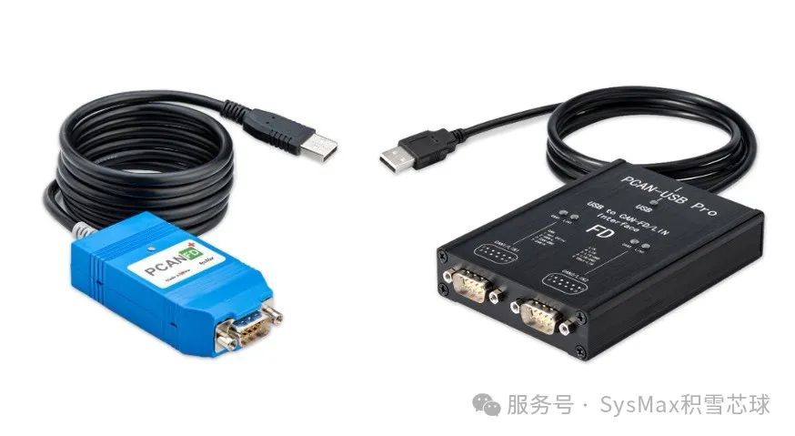 This article will explain how to test using the PCAN-FD device in the EcuBus-Pro software environment. More usage of EcuBus-Pro can be found in the software user documentation:
https://app.whyengineer.com/docs/um/can/can.html
Environment Preparation
-
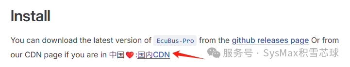
Software Download
Official download link for EcuBus-Pro: https://app.whyengineer.com/docs/about/install.html
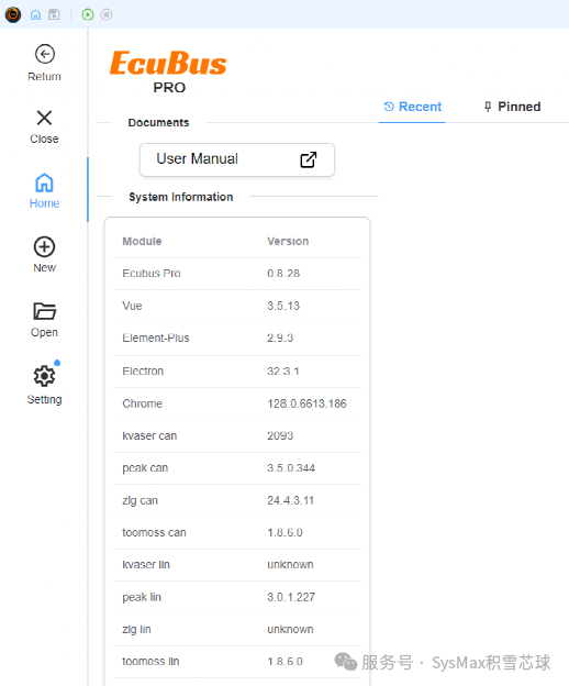
After installation, the software interface is as follows
-
PCAN Driver Installation
If you already have the driver, you can skip this part.
1. Obtain the PEAK-System_Driver-Setup installation package
2. Run the installer in the package to install
3. Connect the adapter to the PC, Windows will detect the hardware, and the driver installation will be complete
Basic Usage of EcuBus-Pro
-
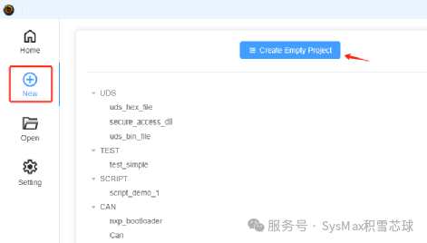
Create Project
Create a new empty project by clicking New, then click Create Empty Project.
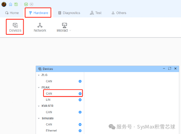
- Add device channels to the software project by clicking Hardware—>Devices, and in the pop-up window, add according to your device; here we choose the PEAK CAN device.
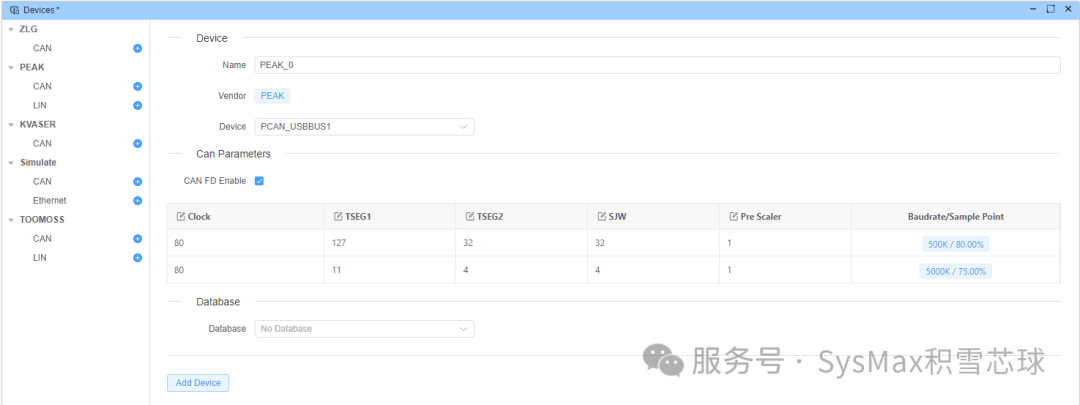
Bind the device channel to the hardware device
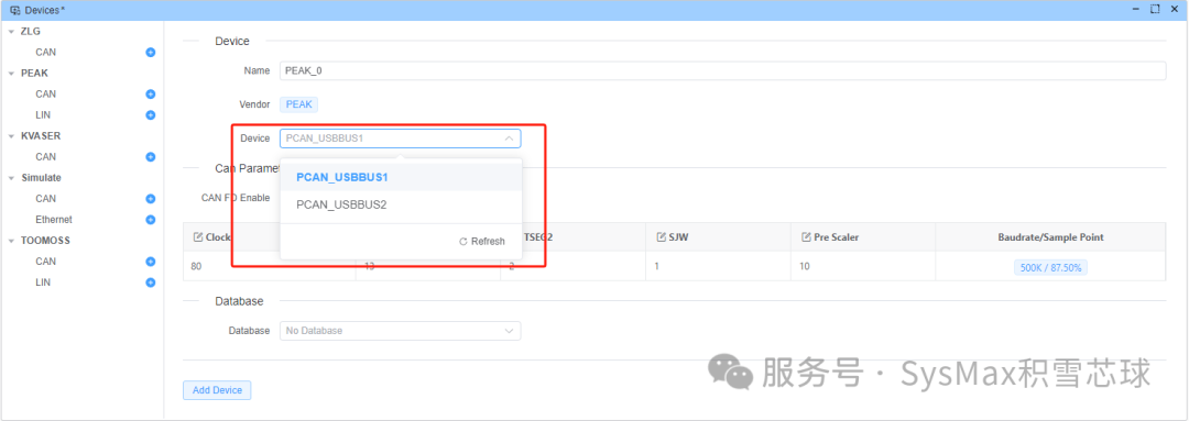
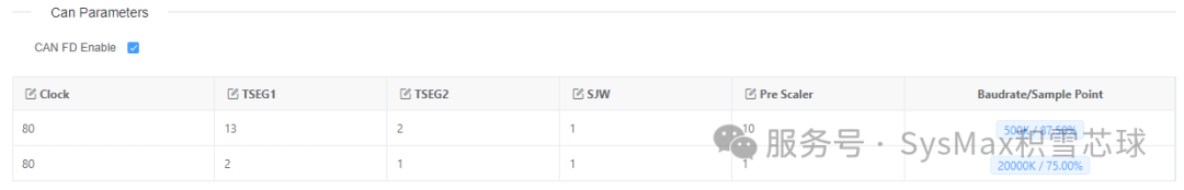
To use the CAN-FD format, check the CAN FD Enable option
It is important to note the baud rate settings; EcuBus-Pro only provides default configurations of 500kbits/2Mbits, and the default configuration of the arbitration segment and data segment PreScaler is inconsistent, which can lead to unstable communication.
If you are not clear about the baud rate configuration, we have detailed explanations of baud rates and simple configuration methods in another article. Easily handle CAN bus baud rate configuration
After setting the correct baud rate parameters, click Add Device to add the device.
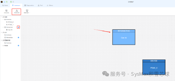
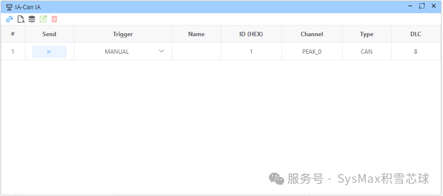
- Add an interactor; the role of the interactor is to manage the frames to be sent.
Click Network, then click the plus sign next to Interactive in the window to add an interactor. You can also click the Interact icon in the taskbar or click the lower left corner of the generated interaction pattern to open the interactor configuration window.
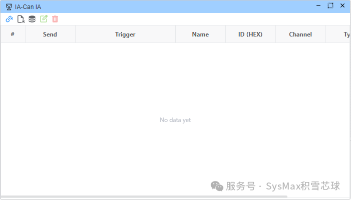
In the interactor configuration window, the top row from left to right is: link device, create frame, import from database, modify frame, delete frame.
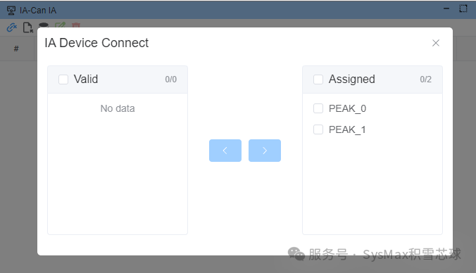
First, click link device to bind the interactor to the device; the left box shows available devices, select and move to the right box for allocation.
After completing the device binding, add frame information in the interactor, which can be modified according to needs, including trigger conditions, frame name, frame ID, channel, frame type, number of bytes to send, whether to enable BRS, modify Data, etc.
-
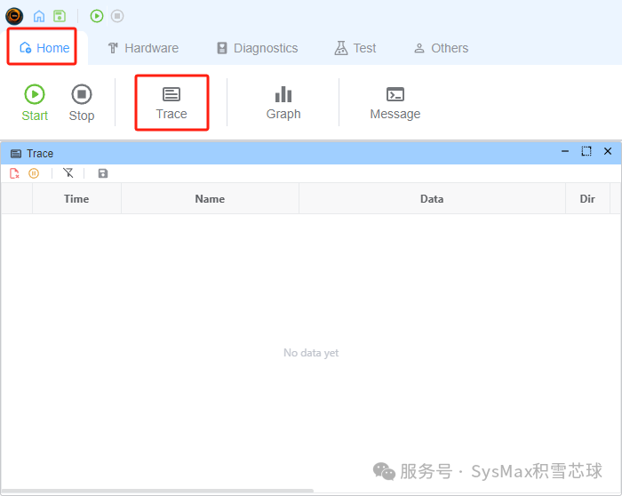
Open the trace interface by clicking Home——Trace; a window will pop up where you can view the message information on the CAN bus.
- Send and Receive Test
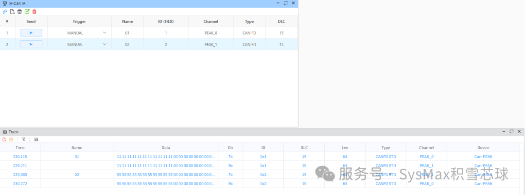
After completing the above operations, the basic environment of EcuBus-Pro and PCAN-FD is now set up, and we can proceed with the send and receive operations.
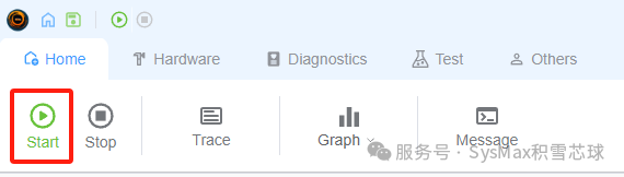
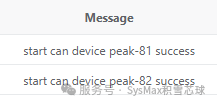
Click Start to begin; the information bar will indicate that the device has started successfully.
In the interactor, send information, and you can see that the information has been successfully sent in the trace interface.
-
Using PCAN-View for Troubleshooting
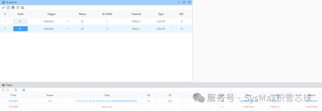
For example, simulating a communication fault by connecting two PCAN FD channels together, setting one channel to standard CAN and the other to CAN FD mode. Let the CAN FD device send FD format messages to the standard CAN channel; at this point, EcuBus-Pro indicates a bus error, but it cannot view the specific error reason (PCAN’s error frame display is not supported).
When using PCAN devices simultaneously in EcuBus-Pro, you can also connect PCAN-View to monitor the device and even send data. This method can help us diagnose errors.
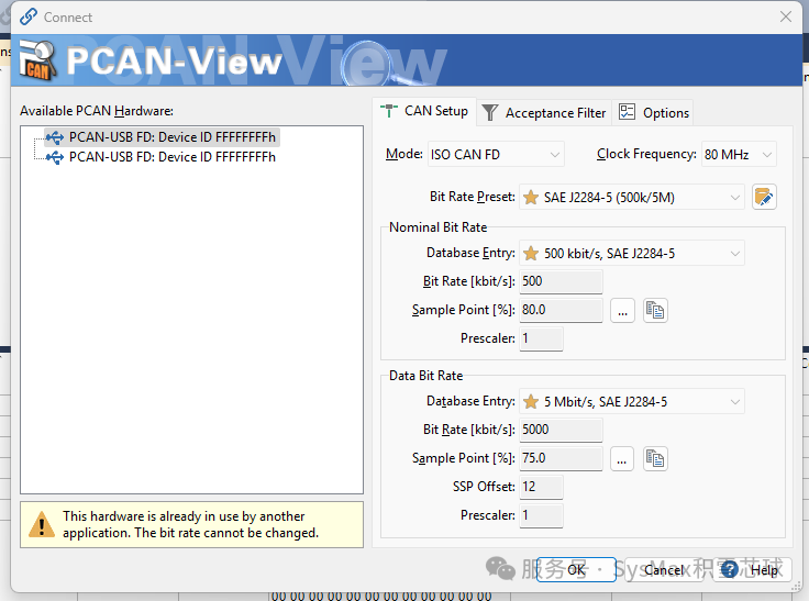
Open the PCAN-View software, select the device, and it will indicate that the hardware is occupied by another application, and the baud rate cannot be modified, but clicking “OK” still allows you to connect to this device with PCAN-View.
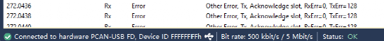
In the PCAN-View trace interface, you can view the response error frames to locate the fault cause.
From this example, we can conclude that using PCAN-View can greatly assist in diagnostics when using other tools.
Conclusion
This article explains the basic usage of the EcuBus-Pro software and how to use it in conjunction with the PCAN-FD device, as well as sharing methods for connecting PCAN-View for assistance. There are many other more professional features of the software waiting for everyone to explore.