“In the field of signal integrity, TDR testing and impedance matching are core technologies to ensure the reliability of high-speed circuits, and the two are closely related and indispensable.”
01 Impedance Matching
—
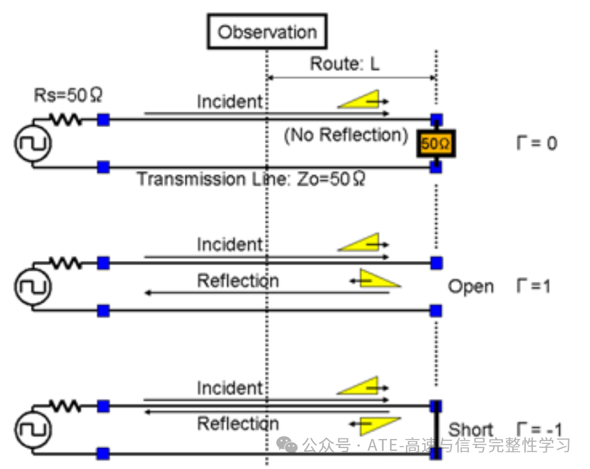
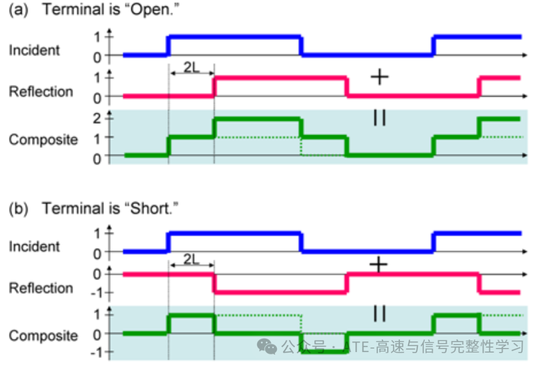
- Reflection Coefficient: As shown in the figure below, when an incident signal is transmitted to a transmission line, it propagates towards the end of the line. When Γ=0, the characteristic impedance of the line is well terminated, and the entire incident signal is absorbed by the terminal impedance, resulting in no reflection; when Γ=1, the output port remains open, and the input signal is reflected 100% with the same polarity; when Γ=-1, the output port remains shorted, and the input signal is reflected with the opposite polarity.
 *(Image from Mixed_Signal_Lecture Hideo Okawara)
02 TDR
—
-
Traditional Time Domain Reflectometry (TDR) is an electronic measurement technology based on radar principles, primarily used to locate discontinuities in the impedance of transmission lines (PCB traces, coaxial cables, etc.) and measure their distances.
-
This article will mathematically model the transmission line based on the theory documented by Hideo Okawara in DSP-Based Testing, observing the results to understand TDR testing.
1. Model the transmission line equation using the ABCD matrix to obtain the relationship between the input voltage V1 and the output voltage V2.
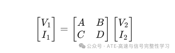 V1, I1 are the voltage and current at the input end, V2, I2 are the voltage and current at the output end, and ABCD are the elements of the matrix. 2. List the voltage measurement formulas based on the transmission line model.
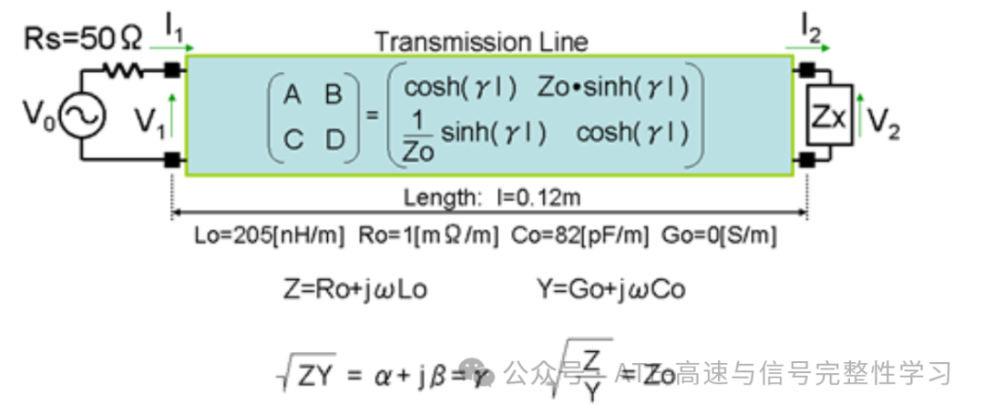 *(Image from Mixed_Signal_Lecture Hideo Okawara) 3. Organizing gives: V2 = I2*Zx V0 = I1*Rs + V1 V1 = ((A*Zx+B) / (Rs*(C*Zx+D)+ (A*Zx+B))) * V0 V2: terminal voltage; V1: measurement point voltage; V0: input voltage; 4. Simulation modeling a. Perform FFT transformation on the Vo time-domain step signal; b. Multiply the transmission line model at each frequency point with the FFT transformed step signal to obtain the frequency domain voltage V1 at the measurement point; c. Perform IFFT inverse transformation on V1 to obtain the time-domain waveform;
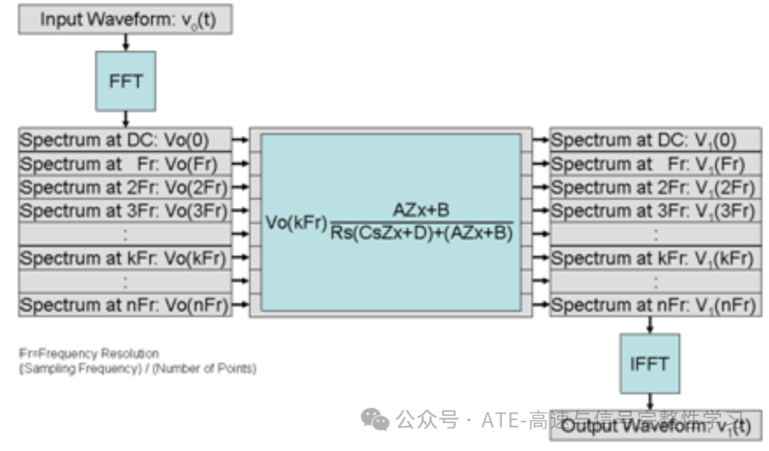 *(Image from Mixed_Signal_Lecture Hideo Okawara) 5. Python simulation results
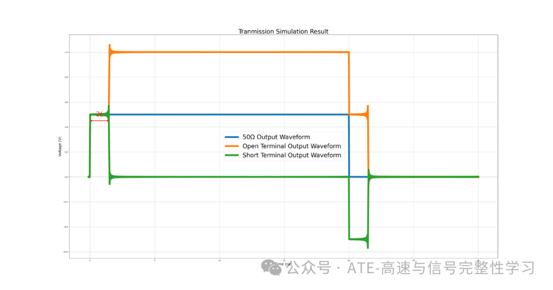 We observed that when the terminal resistance is mismatched, reflections occur at the observation point. Based on the model, the transmission line distance for TDR measurement can also be estimated.,The red double arrows in the figure indicate twice the transmission time.
- Conclusion:
- TDR instruments are based on this principle, generating a step signal with a fast rising edge. The signal propagates along the transmission line and reflects when encountering impedance discontinuities, with the reflected signal returning along the original path to the TDR receiver.
- It is also possible to actively create an open circuit at the terminal to calculate the transmission line delay, such as the common Fixture Delay test in ATE.
03 LTSpice Modeling to Understand the Transmission Process
—
-
In LTSpice, a multi-section LC is used to simulate a lossless transmission line (with resistance Ro and conductance Go equal to 0). Due to the conditions in the Python simulation (0.12m), it is difficult to observe reflections in actual LTSpice (the time is too short), so a 1m transmission line is simulated with a 10-stage LC cascading network.
-
Simulation Results
The green waveform measurement point is at the front end of the power supply internal resistance R1.
The pink waveform measurement point is at the front end of the first LC stage.
The red waveform measurement point is at the front end of the load resistance R2.
The time delay of the transmission line is marked by the dashed line.
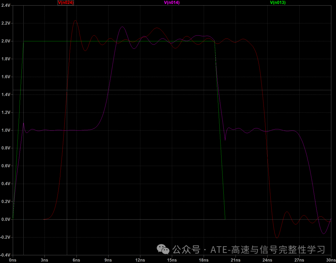
Analyzing with the terminal open (circuit diagram below):
1. Expected transmission line delay Td = sqrt(Lo*Co) *1e9 ns, consistent with LTSpice results.
2. The impedance of the LC cascading network Zo = sqrt(Lo/Co).
3. The transmission process of the step signal can be seen as propagating along the LC cascading network, alternating between inductor charging (establishing current) and capacitor charging (establishing voltage). When the terminal is open, the current cannot pass through, resulting in a full reflection with the same polarity, causing the voltage to double (for specific principles, refer to the wave equation).
