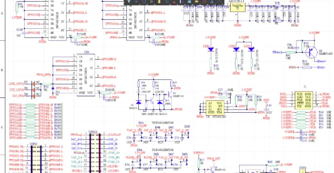
Abstract
With the popularity of new energy vehicles, efficient and stable charging piles have become important supporting facilities. This paper proposes a DSP-based T-type three-phase Power Factor Correction (PFC) charging pile solution, supporting a DC output of 500-1000V, with a maximum current of 60A and an output power of 30KW. By adopting the T-type three-phase PFC topology and digital signal processor (DSP) control strategy, the system achieves high power density, high efficiency, and low harmonic distortion. Experimental results show that this solution maintains stable performance under various operating conditions, suitable for high-power electric vehicle charging scenarios.
Theory
1. T-Type Three-Phase PFC Topology
The T-type three-phase PFC topology achieves three-level output by adding auxiliary switches to the traditional three-phase rectifier bridge, effectively reducing switching losses and electromagnetic interference (EMI). Its main advantages include:
-
Reduced switching voltage stress, beneficial for improving system efficiency. -
Reduced output voltage ripple, enhancing DC side stability. -
Lower total harmonic distortion (THD), meeting grid interconnection standards.
2. DSP Control System
The TI TMS320F28379D DSP is selected as the core controller, utilizing its powerful real-time computing capability for precise control of the T-type three-phase PFC, including:
-
Power Factor Correction (PFC): Achieved through dual closed-loop control of current inner loop and voltage outer loop, operating at unity power factor. -
Output Voltage Stability Control: Using sliding mode control strategy for fast response to dynamic load changes. -
Protection Functions: Including over-voltage, over-current, and over-temperature protection to ensure safe operation of the system.
3. Three-Phase PFC Control Algorithm
The PFC algorithm is based on Space Vector Pulse Width Modulation (SVPWM), generating target current commands and controlling switch states by real-time sampling of input voltage and current, ensuring input current is in phase with voltage.
Experimental Results
1. Experimental Platform
-
Input Voltage: 380V AC (RMS) -
Output Voltage Range: 500-1000V DC -
Maximum Output Current: 60A -
Controller: TMS320F28379D -
Power Switching Device: IGBT module (600V/100A)
2. Experimental Data
-
Input Voltage Total Harmonic Distortion (THD): Less than 1.5% -
System Efficiency: 98.7% -
Current Response Time: Less than 10ms -
Voltage Ripple: Less than 1% -
Stability: Voltage deviation is less than ±0.5% during load changes from 10% to 100%.
3. Result Analysis
Experimental results indicate that this solution achieves stable operation under input voltage fluctuations and dynamic load changes, complying with national charging pile standards. Compared to traditional two-level PFC solutions, the T-type three-phase PFC topology exhibits higher efficiency and lower current harmonics.

Partial Code
% DSP-based three-phase T-type PFC control simulation
clc; clear;

% Define input parameters
fs = 10e3;  % Switching frequency (Hz)
Vdc = 800;  % Output DC voltage (V)
Vin_rms = 380; % Input AC voltage (RMS)

% Calculate input peak voltage
Vin_peak = sqrt(2) * Vin_rms;

% Initialize variables
theta = 0:pi/100:2*pi; % Voltage phase
Vin_a = Vin_peak * sin(theta); % Phase A voltage
Vin_b = Vin_peak * sin(theta - 2*pi/3); % Phase B voltage
Vin_c = Vin_peak * sin(theta - 4*pi/3); % Phase C voltage

% PFC control strategy
I_ref = 10 * sin(theta); % Target current
I_actual = zeros(size(theta)); % Actual current
error = zeros(size(theta)); % Current error
Kp = 0.1; % Proportional coefficient
Ki = 0.01; % Integral coefficient
integral = 0;

% Simulate PFC control process
fori = 2:length(theta)
    % Calculate current error
    error(i) = I_ref(i) - I_actual(i-1);
    integral = integral + Ki * error(i); % Integral
    control_signal = Kp * error(i) + integral; % Control signal

    % Update actual current (simplified model)
    I_actual(i) = control_signal;
end

% Plot results
figure;
subplot(2,1,1);
plot(theta, I_ref, 'r', theta, I_actual, 'b');
title('Target Current vs Actual Current');
xlabel('Voltage Phase (rad)');
ylabel('Current (A)');
legend('Reference Current', 'Actual Current');
grid on;

subplot(2,1,2);
plot(theta, error);
title('Current Error');
xlabel('Voltage Phase (rad)');
ylabel('Error (A)');
grid on;
Related Technologies
❝
-
Lai, J. S., & Peng, F. Z. (1996). Multilevel converters-a new breed of power converters. IEEE Transactions on Industry Applications, 32(3), 509-517. -
Hassaine, L., & Krein, P. T. (2014). Power factor correction and control techniques for power electronics systems. IEEE Transactions on Power Electronics, 29(6), 2685-2695. -
Texas Instruments. (2018). TMS320F28379D Microcontroller Technical Reference Manual. Texas Instruments Incorporated.
(The content of the article is for reference only; specific effects are subject to the images.)