Produced by 21ic Forum Naluo MimiWebsite: bbs.21ic.comAs is my style, let me ramble a bit at the beginning:With nothing much to do and not wanting to tackle anything too difficult, I decided to play around with a development board that has been gathering dust.Last year, I won a development board based on the MM32L073 microcontroller during an event hosted by Lingdong, model eMiniBoard MB-023. At that time, I wrote an unboxing and serial port test review. Now, I am picking it up again to play with some small applications. Due to the limited sensors I have on hand, I can only create an air quality monitoring device, which mainly includes three functions: air temperature detection, air humidity detection, and PM2.5 concentration detection.However, I ran into issues while debugging the temperature and humidity detection. The sensor I used is the DHT11 module, which requires microsecond-level delays during operation. Unfortunately, I couldn’t find a microsecond delay function in the MM32L073 library. Of course, excluding the empty function for coarse delays, using SysTick can only achieve millisecond-level delays. I attempted to write a microsecond delay function, but it simply did not work, as detailed below:
void delay_init()
{
    RCC_ClocksTypeDef RCC_Clocks;
    if (SysTick_Config(SystemCoreClock / 1000))
    {
        /* Capture error */
        while (1);
    }
    /* Configure the SysTick handler priority */
    NVIC_SetPriority(SysTick_IRQn, 0x0);//SysTick interrupt priority setting
}
The above is the delay function initialization from the official library. In the SysTick_Config function, the system clock (48M) is divided by 1000, causing SysTick to trigger an interrupt every 1 millisecond. If I divide SystemCoreClock by 1000000, it should trigger an interrupt every 1 microsecond, but this causes the delay function to hang. After debugging, I found that the program hangs at the SysTick_Config() function. Continuing to trace:
__STATIC_INLINE uint32_t SysTick_Config(uint32_t ticks)
{
  if ((ticks - 1) > SysTick_LOAD_RELOAD_Msk)
          return (1);      /* Reload value impossible */
  SysTick->LOAD  = ticks - 1;                                  /* set reload register */
  NVIC_SetPriority (SysTick_IRQn, (1<<__NVIC_PRIO_BITS) - 1);  /* set Priority for SysTick Interrupt */
  SysTick->VAL   = 0;                                          /* Load the SysTick Counter Value */
  SysTick->CTRL  = SysTick_CTRL_CLKSOURCE_Msk |
                   SysTick_CTRL_TICKINT_Msk   |
                   SysTick_CTRL_ENABLE_Msk;                    /* Enable SysTick IRQ and SysTick Timer */
  return (0);                                                  /* Function successful */
}
The program hangs at SysTick->LOAD = ticks – 1; that is, writing the reload value register of SysTick with 47 causes it to hang. I remember seeing somewhere that this value cannot be less than 255, otherwise it will automatically write 255. After testing, this was indeed the case. I did not delve deeper into this issue and switched to using a timer. PS: This issue does not exist in STM32F030 and GD32E230; I wonder what the reason is. I hope someone knowledgeable can provide some insight.After testing, the timer interrupt cannot achieve an interrupt every 1 microsecond, regardless of how it is set; the timer can only interrupt approximately every 3 microseconds. This solution is discarded.Having come this far, I cannot give up halfway, so I bought a minimum system board MM32F103CBT6 for over seventy yuan. The price increase is really outrageous!After all that rambling, we can finally get to the main content.This article consists of three modules: an OLED module, using simulated IIC drive; a DHT11 temperature and humidity module, with IO port read and write operations; and a Sharp GP2Y10 dust sensor, with UART operations.OLED DriverI have two 7-pin 0.96-inch OLED screens, but neither worked during testing, and I couldn’t get them to light up no matter what. So, while buying the minimum system board, I also bought a 4-pin 0.96-inch OLED screen, which also failed to work during testing. After trying several methods and using an STM32 board for testing, I found that the Dupont wire was broken internally, which was not visible from the outside. I really have no words to express my frustration. There is no need to elaborate on the introduction of this screen; there is plenty of information online. Here, I will share my driver. oled.c
#include "oled.h"
#include "stdlib.h"
#include "oledfont.h"
#include "delay.h"
// OLED memory
// The format is as follows.
// [0]0 1 2 3 ... 127
// [1]0 1 2 3 ... 127
// [2]0 1 2 3 ... 127
// [3]0 1 2 3 ... 127
// [4]0 1 2 3 ... 127
// [5]0 1 2 3 ... 127
// [6]0 1 2 3 ... 127
// [7]0 1 2 3 ... 127
/**********************************************
// IIC Start
**********************************************/
void IIC_Start()
{
OLED_SCLK_Set();
OLED_SDIN_Set();
OLED_SDIN_Clr();
OLED_SCLK_Clr();
}
/**********************************************
// IIC Stop
**********************************************/
void IIC_Stop()
{
OLED_SCLK_Set();
OLED_SDIN_Clr();
OLED_SDIN_Set();
}
void IIC_Wait_Ack()
{
OLED_SCLK_Set();
OLED_SCLK_Clr();
}
/**********************************************
// IIC Write byte
**********************************************/
void Write_IIC_Byte(unsigned char IIC_Byte)
{
unsigned char i;
unsigned char m,da;
da=IIC_Byte;
OLED_SCLK_Clr();
for(i=0;i<8;i++)
{
m=da;
m=m&0x80;
if(m==0x80)
{OLED_SDIN_Set();}
else OLED_SDIN_Clr();
da=da<<1;
OLED_SCLK_Set();
OLED_SCLK_Clr();
}
}
/**********************************************
// IIC Write Command
**********************************************/
void Write_IIC_Command(unsigned char IIC_Command)
{
IIC_Start();
Write_IIC_Byte(0x78); // Slave address, SA0=0
IIC_Wait_Ack();
Write_IIC_Byte(0x00); // write command
IIC_Wait_Ack();
Write_IIC_Byte(IIC_Command);
IIC_Wait_Ack();
IIC_Stop();
}
/**********************************************
// IIC Write Data
**********************************************/
void Write_IIC_Data(unsigned char IIC_Data)
{
IIC_Start();
Write_IIC_Byte(0x78); // D/C#=0; R/W#=0
IIC_Wait_Ack();
Write_IIC_Byte(0x40); // write data
IIC_Wait_Ack();
Write_IIC_Byte(IIC_Data);
IIC_Wait_Ack();
IIC_Stop();
}
void OLED_WR_Byte(unsigned dat,unsigned cmd)
{
if(cmd)
{
Write_IIC_Data(dat);
}
else {
Write_IIC_Command(dat);
}
}
/********************************************
// fill_Picture
********************************************/
void fill_picture(unsigned char fill_Data)
{
unsigned char m,n;
for(m=0;m<8;m++)
{
OLED_WR_Byte(0xb0+m,0); // page0-page1
OLED_WR_Byte(0x00,0); // low column start address
OLED_WR_Byte(0x10,0); // high column start address
for(n=0;n<128;n++)
{
OLED_WR_Byte(fill_Data,1);
}
}
}
/***********************Delay****************************************/
void Delay_50ms(unsigned int Del_50ms)
{
unsigned int m;
for(;Del_50ms>0;Del_50ms--)
for(m=6245;m>0;m--);
}
void Delay_1ms(unsigned int Del_1ms)
{
unsigned char j;
while(Del_1ms--)
{
for(j=0;j<123;j++);
}
}
// Coordinate setting
void OLED_Set_Pos(unsigned char x, unsigned char y)
{ OLED_WR_Byte(0xb0+y,OLED_CMD);
OLED_WR_Byte(((x&0xf0)>>4)|0x10,OLED_CMD);
OLED_WR_Byte((x&0x0f),OLED_CMD);
}
// Turn on OLED display
void OLED_Display_On(void)
{
OLED_WR_Byte(0X8D,OLED_CMD); // SET DCDC command
OLED_WR_Byte(0X14,OLED_CMD); // DCDC ON
OLED_WR_Byte(0XAF,OLED_CMD); // DISPLAY ON
}
// Turn off OLED display
void OLED_Display_Off(void)
{
OLED_WR_Byte(0X8D,OLED_CMD); // SET DCDC command
OLED_WR_Byte(0X10,OLED_CMD); // DCDC OFF
OLED_WR_Byte(0XAE,OLED_CMD); // DISPLAY OFF
}
// Clear screen function, after clearing the screen, the entire screen is black! It looks like it is not lit!!!
void OLED_Clear(void)
{
u8 i,n;
for(i=0;i<8;i++)
{
OLED_WR_Byte (0xb0+i,OLED_CMD); // set page address (0~7)
OLED_WR_Byte (0x00,OLED_CMD); // set display position—column low address
OLED_WR_Byte (0x10,OLED_CMD); // set display position—column high address
for(n=0;n<128;n++)OLED_WR_Byte(0,OLED_DATA);
} // update display
}
void OLED_On(void)
{
u8 i,n;
for(i=0;i<8;i++)
{
OLED_WR_Byte (0xb0+i,OLED_CMD); // set page address (0~7)
OLED_WR_Byte (0x00,OLED_CMD); // set display position—column low address
OLED_WR_Byte (0x10,OLED_CMD); // set display position—column high address
for(n=0;n<128;n++)OLED_WR_Byte(1,OLED_DATA);
} // update display
}
// Display a character at a specified position, including partial characters
// x:0~127
// y:0~63
// mode:0, inverse display; 1, normal display
// size: choose font 16/12
void OLED_ShowChar(u8 x,u8 y,u8 chr,u8 Char_Size)
{
unsigned char c=0,i=0;
c=chr-' ';// get the offset value
if(x>Max_Column-1){x=0;y=y+2;}
if(Char_Size ==16)
{
OLED_Set_Pos(x,y);
for(i=0;i<8;i++)
OLED_WR_Byte(F8X16[c*16+i],OLED_DATA);
OLED_Set_Pos(x,y+1);
for(i=0;i<8;i++)
OLED_WR_Byte(F8X16[c*16+i+8],OLED_DATA);
}
else {
OLED_Set_Pos(x,y);
for(i=0;i<6;i++)
OLED_WR_Byte(F6x8[c][i],OLED_DATA);
}
}
// m^n function
u32 oled_pow(u8 m,u8 n)
{
u32 result=1;
while(n--)result*=m;
return result;
}
// Display two numbers
// x,y : starting coordinates
// len : number of digits
// size: font size
// mode: mode 0, fill mode; 1, overlay mode
// num: value (0~4294967295);
void OLED_ShowNum(u8 x,u8 y,u32 num,u8 len,u8 size2)
{
u8 t,temp;
u8 enshow=0;
for(t=0;t<len;t++)
{
temp=(num/oled_pow(10,len-t-1))%10;
if(enshow==0&&t<(len-1))
{
if(temp==0)
{
OLED_ShowChar(x+(size2/2)*t,y,' ',size2);
continue;
}else enshow=1;
}
OLED_ShowChar(x+(size2/2)*t,y,temp+'0',size2);
}
}
// Display a character string
void OLED_ShowString(u8 x,u8 y,u8 *chr,u8 Char_Size)
{
unsigned char j=0;
while (chr[j]!='\0')
{ OLED_ShowChar(x,y,chr[j],Char_Size);
x+=8;
if(x>120){x=0;y+=2;}
j++;
}
}
// Display Chinese characters
void OLED_ShowCHinese(u8 x,u8 y,u8 no)
{
u8 t,adder=0;
OLED_Set_Pos(x,y);
for(t=0;t<16;t++)
{
OLED_WR_Byte(Hzk[2*no][t],OLED_DATA);
adder+=1;
}
OLED_Set_Pos(x,y+1);
for(t=0;t<16;t++)
{
OLED_WR_Byte(Hzk[2*no+1][t],OLED_DATA);
adder+=1;
}
}
/***********Function Description: Display BMP image 128×64 starting point coordinates (x,y), x range 0~127, y page range 0~7*****************/
void OLED_DrawBMP(unsigned char x0, unsigned char y0,unsigned char x1, unsigned char y1,unsigned char BMP[])
{
unsigned int j=0;
unsigned char x,y;
if(y1%8==0) y=y1/8;
else y=y1/8+1;
for(y=y0;y<y1;y++)
{
OLED_Set_Pos(x0,y);
for(x=x0;x<x1;x++)
{
OLED_WR_Byte(BMP[j++],OLED_DATA);
}
}
}
// Initialize SSD1306
void OLED_Init(void)
{
GPIO_InitTypeDef GPIO_InitStructure;
RCC_APB2PeriphClockCmd(RCC_APB2Periph_GPIOA, ENABLE); // Enable A port clock
GPIO_InitStructure.GPIO_Pin = GPIO_Pin_5|GPIO_Pin_7;
GPIO_InitStructure.GPIO_Mode = GPIO_Mode_Out_PP; // Push-pull output
GPIO_InitStructure.GPIO_Speed = GPIO_Speed_50MHz;// Speed 50MHz
GPIO_Init(GPIOA, &GPIO_InitStructure); // Initialize GPIOD3,6
GPIO_SetBits(GPIOA,GPIO_Pin_5|GPIO_Pin_7);
delay_ms(800);
OLED_WR_Byte(0xAE,OLED_CMD);//--display off
OLED_WR_Byte(0x00,OLED_CMD);//---set low column address
OLED_WR_Byte(0x10,OLED_CMD);//---set high column address
OLED_WR_Byte(0x40,OLED_CMD);//--set start line address
OLED_WR_Byte(0xB0,OLED_CMD);//--set page address
OLED_WR_Byte(0x81,OLED_CMD); // contract control
OLED_WR_Byte(0xFF,OLED_CMD);//--128
OLED_WR_Byte(0xA1,OLED_CMD);//set segment remap
OLED_WR_Byte(0xA6,OLED_CMD);//--normal / reverse
OLED_WR_Byte(0xA8,OLED_CMD);//--set multiplex ratio(1 to 64)
OLED_WR_Byte(0x3F,OLED_CMD);//--1/32 duty
OLED_WR_Byte(0xC8,OLED_CMD);//Com scan direction
OLED_WR_Byte(0xD3,OLED_CMD);//-set display offset
OLED_WR_Byte(0x00,OLED_CMD);//
OLED_WR_Byte(0xD5,OLED_CMD);//set osc division
OLED_WR_Byte(0x80,OLED_CMD);//
OLED_WR_Byte(0xD8,OLED_CMD);//set area color mode off
OLED_WR_Byte(0x05,OLED_CMD);//
OLED_WR_Byte(0xD9,OLED_CMD);//Set Pre-Charge Period
OLED_WR_Byte(0xF1,OLED_CMD);//
OLED_WR_Byte(0xDA,OLED_CMD);//set com pin configuration
OLED_WR_Byte(0x12,OLED_CMD);//
OLED_WR_Byte(0xDB,OLED_CMD);//set Vcomh
OLED_WR_Byte(0x30,OLED_CMD);//
OLED_WR_Byte(0x8D,OLED_CMD);//set charge pump enable
OLED_WR_Byte(0x14,OLED_CMD);//
OLED_WR_Byte(0xAF,OLED_CMD);//--turn on oled panel
}
oled.h
#ifndef __OLED_H
#define __OLED_H
#include "sys.h"
#include "stdlib.h"
#define OLED_MODE 0
#define SIZE 8
#define XLevelL                0x00
#define XLevelH                0x10
#define Max_Column        128
#define Max_Row                64
#define        Brightness        0xFF
#define X_WIDTH         128
#define Y_WIDTH         64
//-----------------OLED IIC port definition----------------
#define OLED_SCLK_Clr() GPIO_ResetBits(GPIOA,GPIO_Pin_5)//SCL
#define OLED_SCLK_Set() GPIO_SetBits(GPIOA,GPIO_Pin_5)
#define OLED_SDIN_Clr() GPIO_ResetBits(GPIOA,GPIO_Pin_7)//SDA
#define OLED_SDIN_Set() GPIO_SetBits(GPIOA,GPIO_Pin_7)
#define OLED_CMD  0        // write command
#define OLED_DATA 1        // write data
// OLED control functions
void OLED_WR_Byte(unsigned dat,unsigned cmd);
void OLED_Display_On(void);
void OLED_Display_Off(void);
void OLED_Init(void);
void OLED_Clear(void);
void OLED_DrawPoint(u8 x,u8 y,u8 t);
void OLED_Fill(u8 x1,u8 y1,u8 x2,u8 y2,u8 dot);
void OLED_ShowChar(u8 x,u8 y,u8 chr,u8 Char_Size);
void OLED_ShowNum(u8 x,u8 y,u32 num,u8 len,u8 size);
void OLED_ShowString(u8 x,u8 y, u8 *p,u8 Char_Size);
void OLED_Set_Pos(unsigned char x, unsigned char y);
void OLED_ShowCHinese(u8 x,u8 y,u8 no);
void OLED_DrawBMP(unsigned char x0, unsigned char y0,unsigned char x1, unsigned char y1,unsigned char BMP[]);
void Delay_50ms(unsigned int Del_50ms);
void Delay_1ms(unsigned int Del_1ms);
void fill_picture(unsigned char fill_Data);
void Picture();
void IIC_Start();
void IIC_Stop();
void Write_IIC_Command(unsigned char IIC_Command);
void Write_IIC_Data(unsigned char IIC_Data);
void Write_IIC_Byte(unsigned char IIC_Byte);
void IIC_Wait_Ack();
#endif
There is one point to note here: Write_IIC_Byte(0x78); writes the IIC address, and this address is generally set to 0x78, which can be modified via the resistors on the back of the screen.DHT11 Temperature and Humidity ModuleThe DHT11 module uses single-wire communication, allowing data exchange with just one data line. After the MCU sends a data request, it waits for the module to return data. The time for one communication is about 4ms, which is relatively slow, making it suitable only for general application scenarios. A complete data transmission consists of 40 bits, formatted as follows:Data format: 8-bit humidity integer data + 8-bit humidity decimal data + 8-bit temperature integer data + 8-bit temperature decimal data + 8-bit checksum. When the data is transmitted correctly, the checksum equals the last 8 bits of the result obtained from “8-bit humidity integer data + 8-bit humidity decimal data + 8-bit temperature integer data + 8-bit temperature decimal data”.After the user MCU sends a start signal, the DHT11 transitions from low-power mode to high-speed mode, waiting for the host’s start signal to end before sending a response signal and transmitting 40 bits of data, triggering a signal collection. The user can choose to read part of the data. In low-power mode, the DHT11 will not actively collect temperature and humidity data unless it receives the host’s start signal. After collecting data, it transitions back to low-speed mode.The bus idle state is high, and the host pulls the bus low, waiting for the DHT11’s response. The host must pull the bus low for more than 18 milliseconds to ensure the DHT11 can detect the start signal. After receiving the host’s start signal, the DHT11 waits for the host’s start signal to end, then sends an 80us low-level response signal. After the host’s start signal ends, it waits for 20-40us before reading the DHT11’s response signal. After sending the start signal, the host can switch to input mode or output high level; the bus is pulled high by a pull-up resistor.Based on the above information, we can write the DHT11 code: This module is also included in the examples from the ZhenDian Atom, but they use GPIO bit-banding operations, which cannot be used with the MM32L073. The M0 core seems to lack bit-banding operations, so I can only use pseudo-bit-banding operations or directly modify GPIO input and output using functions. Since I have been playing with the MM32L073 for two days, I will not use bit-banding operations here and will control it directly with functions. DHT11.C
#include "dht11.h"
#include "delay.h"
void DHT11_IO_IN(void)// Temperature and humidity module input function
{
GPIO_InitTypeDef GPIO_InitStructure;
//RCC_AHBPeriphClockCmd(RCC_AHBPeriph_GPIOB,ENABLE);
GPIO_InitStructure.GPIO_Pin=IO_DHT11;
GPIO_InitStructure.GPIO_Mode=GPIO_Mode_IN_FLOATING;
GPIO_Init(GPIO_DHT11,&GPIO_InitStructure);
}
void DHT11_IO_OUT(void)// Temperature and humidity module output function
{
GPIO_InitTypeDef GPIO_InitStructure;
// RCC_AHBPeriphClockCmd(RCC_AHBPeriph_GPIOB,ENABLE);
GPIO_InitStructure.GPIO_Pin=IO_DHT11;
GPIO_InitStructure.GPIO_Speed=GPIO_Speed_50MHz;
GPIO_InitStructure.GPIO_Mode=GPIO_Mode_Out_PP;
GPIO_Init(GPIO_DHT11,&GPIO_InitStructure);
}
// Reset DHT11
void DHT11_Rst(void)
{
DHT11_IO_OUT(); // SET OUTPUT
DHT11_DQ_Low; // DQ=0
delay_ms(20); // Pull low for at least 18ms
DHT11_DQ_High; // DQ=1
delay_us(30); // Host pulls high for 20~40us
}
// Wait for DHT11's response
// Return 1: DHT11 not detected
// Return 0: exists
u8 DHT11_Check(void)
{
u8 retry=0;// Define temporary variable
DHT11_IO_IN();// SET INPUT
while ((GPIO_ReadInputDataBit(GPIO_DHT11,IO_DHT11)==1)&&&retry<100)// DHT11 will pull low for 40~80us
{
retry++;
delay_us(1);
};
if(retry>=100)return 1;
else retry=0;
while ((GPIO_ReadInputDataBit(GPIO_DHT11,IO_DHT11)==0)&&&retry<100)// DHT11 will pull low and then pull high for 40~80us
{
retry++;
delay_us(1);
};
if(retry>=100)return 1;
return 0;
}
// Read a bit from DHT11
// Return value: 1/0
u8 DHT11_Read_Bit(void)
{
u8 retry=0;
while((GPIO_ReadInputDataBit(GPIO_DHT11,IO_DHT11)==1)&&&retry<100)// Wait for low level
{
retry++;
delay_us(1);
}
retry=0;
while((GPIO_ReadInputDataBit(GPIO_DHT11,IO_DHT11)==0)&&&retry<100)// Wait for high level
{
retry++;
delay_us(1);
}
delay_us(40);// Wait 40us
if(GPIO_ReadInputDataBit(GPIO_DHT11,IO_DHT11)==1)
return 1;
else
return 0;
}
// Read a byte from DHT11
// Return value: the data read
u8 dat;
u8 DHT11_Read_Byte(void)
{
u8 i;
dat=0;
for (i=0;i<8;i++)
{
dat<<=1;
dat|=DHT11_Read_Bit();
}
return dat;
}
// Read data from DHT11
// temp: temperature value (range: 0~50°)
// humi: humidity value (range: 20%~90%)
// Return value: 0, normal; 1, read failed
u8 buf[5];
u8 DHT11_Read_Data(u8 *temp,u8 *humi)
{
u8 i;
DHT11_Rst();
if(DHT11_Check()==0)
{
for(i=0;i<5;i++)// Read 40 bits of data
{
buf[i]=DHT11_Read_Byte();
}
if((buf[0]+buf[1]+buf[2]+buf[3])==buf[4])
{
*humi=buf[0];
*temp=buf[2];
}
}else return 1;
return 0;
}
// Initialize DHT11's IO port DQ and check for DHT11's existence
// Return 1: does not exist
// Return 0: exists
u8 DHT11_Init(void)
{
GPIO_InitTypeDef GPIO_InitStructure;
RCC_APB2PeriphClockCmd(RCC_APB2Periph_GPIOB,ENABLE);
GPIO_InitStructure.GPIO_Pin=IO_DHT11;
GPIO_InitStructure.GPIO_Speed=GPIO_Speed_50MHz;
GPIO_InitStructure.GPIO_Mode=GPIO_Mode_Out_PP;
GPIO_Init(GPIO_DHT11,&GPIO_InitStructure);
GPIO_SetBits(GPIO_DHT11,IO_DHT11);
DHT11_Rst(); // Reset DHT11
return DHT11_Check();// Wait for DHT11's response
}
/*****************************************************************/
dht11.h
#ifndef __DHT11_H__
#define __DHT11_H__
#include "sys.h"
#define IO_DHT11 GPIO_Pin_12 // Introduce intermediate variable for easy portability
#define GPIO_DHT11 GPIOB // Introduce intermediate variable for easy portability
#define DHT11_DQ_High GPIO_SetBits(GPIO_DHT11,IO_DHT11)
#define DHT11_DQ_Low  GPIO_ResetBits(GPIO_DHT11,IO_DHT11)
void DHT11_IO_OUT(void);// Temperature and humidity module output function
void DHT11_IO_IN(void); // Temperature and humidity module input function
u8 DHT11_Init(void);  // Initialize DHT11
u8   DHT11_Read_Data(u8 *temp,u8 *humi);// Read temperature and humidity
u8   DHT11_Read_Byte(void);             // Read a byte
u8   DHT11_Read_Bit(void);              // Read a bit
u8   DHT11_Check(void);                 // Check if DHT11 exists
void DHT11_Rst(void);                   // Reset DHT11
#endif
SHARP GP2Y1051AU0F Dust SensorThe dust sensor contains an LED light source and a light-sensitive detector. When dust is present in the air, it scatters the light, and the light-sensitive element detects this scattered light and outputs different voltages. The dust concentration corresponds to different output voltages. This module directly outputs data via UART, allowing for direct reading of the serial data, extracting the voltage value, and calculating the dust concentration value.UART output parameters:Baud rate: 2400 bit/sData transmission format:
| Start bit | Vout(H) | Vout(L) | Vref(H) | Vref(L) | Checksum | End bit |
| 0xAA | e.g., 0x01 | e.g., 0x3A | e.g., 0x00 | e.g., 0x7A | e.g., 0xD0 | 0xFF |
Data processing:Vout = (Vout(H)*256+Vout(L))/1024*5Dust concentration calculation: Ud= A*Vout, where A is the proportional coefficient, generally set to 800.Note: The module data is not output in packets, and the MCU does not need to send commands. Therefore, just connect the module’s TX, and RX can be left floating. It outputs one byte every 10ms, totaling 7 bytes. After the end bit is output, the next start bit will arrive in 10ms, continuing to output the next start bit. Thus, when receiving data, it cannot be done in a packet manner; it must be received one by one and check for the start bit. I adopted enabling the serial port receive interrupt, and after each interrupt trigger, I process the received data:
void UART1_IRQHandler(void)                 // Serial port 1 interrupt service routine
{
    u8 Res;
    if(UART_GetITStatus(UART1, UART_IT_RXIEN)  != RESET) { // Receive interrupt (the received data must end with 0x0d 0x0a)
        UART_ClearITPendingBit(UART1, UART_IT_RXIEN);
        Res = UART_ReceiveData(UART1);  // Read the received data
                PM2_5_DATA_COUNT(Res);
    }
}
After receiving a byte of data, it enters the data processing function PM2_5_DATA_COUNT();
float vout;
void PM2_5_DATA_COUNT(u8 dat)
{
        u16 sum = 0;// Used to calculate checksum
        if(dat==170)// Check start bit, the fixed start bit is 0xAA=170,
        {
                j = 0;
                DST_Buffer[j] = dat;
        }
        else{
                j=j+1;
                DST_Buffer[j] = dat;
                if(j==6)
                {
                        sum = DST_Buffer[1]+DST_Buffer[2]+DST_Buffer[3]+DST_Buffer[4];
                        if(sum==DST_Buffer[5]&&&DST_Buffer[6]==0xFF)
                        {
                        vout = (float)((DST_Buffer[1]*256+DST_Buffer[2]));
                        vout = vout/(1024*5);
                        PM2_5 = 1000*vout;
                        }
                }
        }
}
The variable vout can be defined as a local variable; I have taken it out for debugging purposes, but it should definitely be defined as a floating-point type since the calculated voltage is a decimal. This function is designed to find the start bit and arrange the data according to the data format in the array, making it easier to extract the data for calculations later. Initially, I used DMA for receiving, but the data was jumbled, making it difficult to find the data, so I switched to the serial port interrupt method. If you want to improve accuracy, you can average multiple measurements, but I was too lazy to do that. Main function:
int main(void)
{
        u8 wd=0;
        u8 sd=0;
        delay_init();
        DHT11_Init();
    uart_initwBaudRate(2400);
        OLED_Init();                        // Initialize OLED
        OLED_Clear();
        while(1)
        {
                OLED_ShowString(0,0,"PM2.5:",16);
                OLED_ShowString(0,3,"temp:",16);
                OLED_ShowString(0,6,"humi:",16);
                OLED_ShowString(85,0,"ug/m3",16);
                OLED_ShowString(85,3,"C",16);
                OLED_ShowString(85,6,"%RH",16);
                OLED_ShowNum(45,0,PM2_5,3,16);
                DHT11_Read_Data(&wd,&sd);// Read temperature and humidity values
                OLED_ShowNum(50,3,wd,3,16);
                OLED_ShowNum(50,6,sd,3,16);
        }
}
Since PM2.5 is handled by an interrupt, I added a temperature and humidity reading in the main function, and all the data is printed on the OLED. Finally, let’s take a look at my physical setup.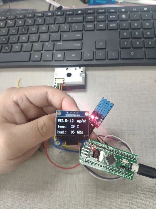 The dynamic image shows the dynamic effect of air quality changes. Since I cannot use smoke indoors, I tested with an electronic cigarette, which does not actually belong to dust, so the value changes are not obvious.This article ends here. Since I was just messing around, the modules I used are quite rough, and there is no casing. I still don’t have the money to buy a 3D printer, so I’ll make do with what I have. It’s a simple effect that many people can achieve; please don’t criticize too harshly.This article is an original work by Naluo Mimi from the 21ic Forum. For material downloads, please click “Read the original text” to download.Copyright belongs to the original author. If there is any infringement, please contact for deletion.