The small airplane’s board is designed like this:
Then I started to lose focus… I sincerely hope some friends can join me to work on this!
I lost focus because I wanted to add a current feedback loop in the motor control, so I wanted to measure the current when using a lithium battery to power the 720 coreless motor with and without propeller. Just when I was about to measure, I found that my multimeter was out of battery, which was quite frustrating. Moreover, my multimeter cannot continuously record data, making it impossible to obtain the discharge curve of the lithium battery, so I decided to make one myself!
Solution One
MCU + ADC + OP AMP
There are many amplifiers specifically designed for current measurement, such as TI’s INA181 and INA199. If the resolution requirement is not high, many MCUs now come with built-in 12-bit ADCs that are sufficient. This solution architecture is quite flexible with a wide selection range. However, it requires developing MCU programs, and the circuit is not simple.
Solution Two
Digital Interface Current Meter/Power Meter Chip
This solution has high integration and a simple circuit, but the selection range is narrower, and the measurement parameters are entirely determined by the chip.
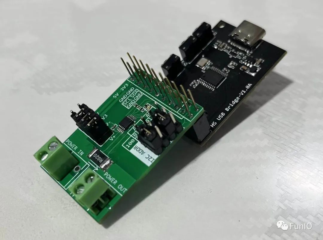
Since I have previously made a CH347 to SPI I2C interface module, let’s go with solution two!
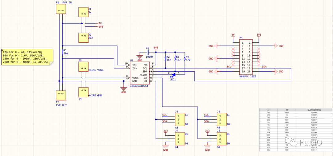
Schematic
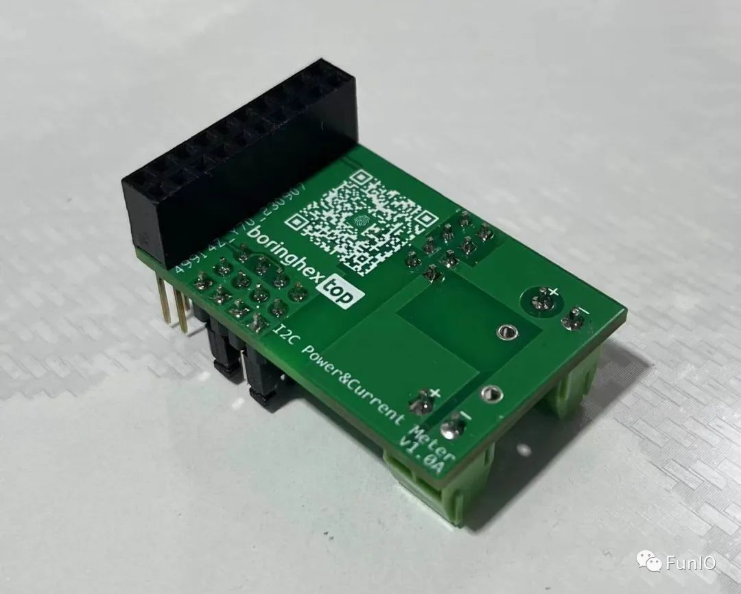
The TI INA226 chip was selected, and the schematic is as follows:
Features
-
Bus voltage sensing range: 0V – 36V -
High-side/low-side current sensing -
Voltage, current, power measurement -
0.1% gain error -
10uV offset -
Configurable measurement averaging -
16 configurable I2C addresses -
2.7V – 5.5V power supply -
2 power rails, selectable as load power supply, when expanded with CH347 high-speed USB bridge module[1], for 3.3V and 5V -
Alert indicator -
Optional remote voltage sensing when not grounded -
Pin compatible with CH347 module, plug and play
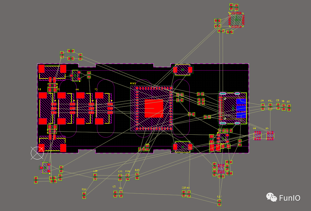
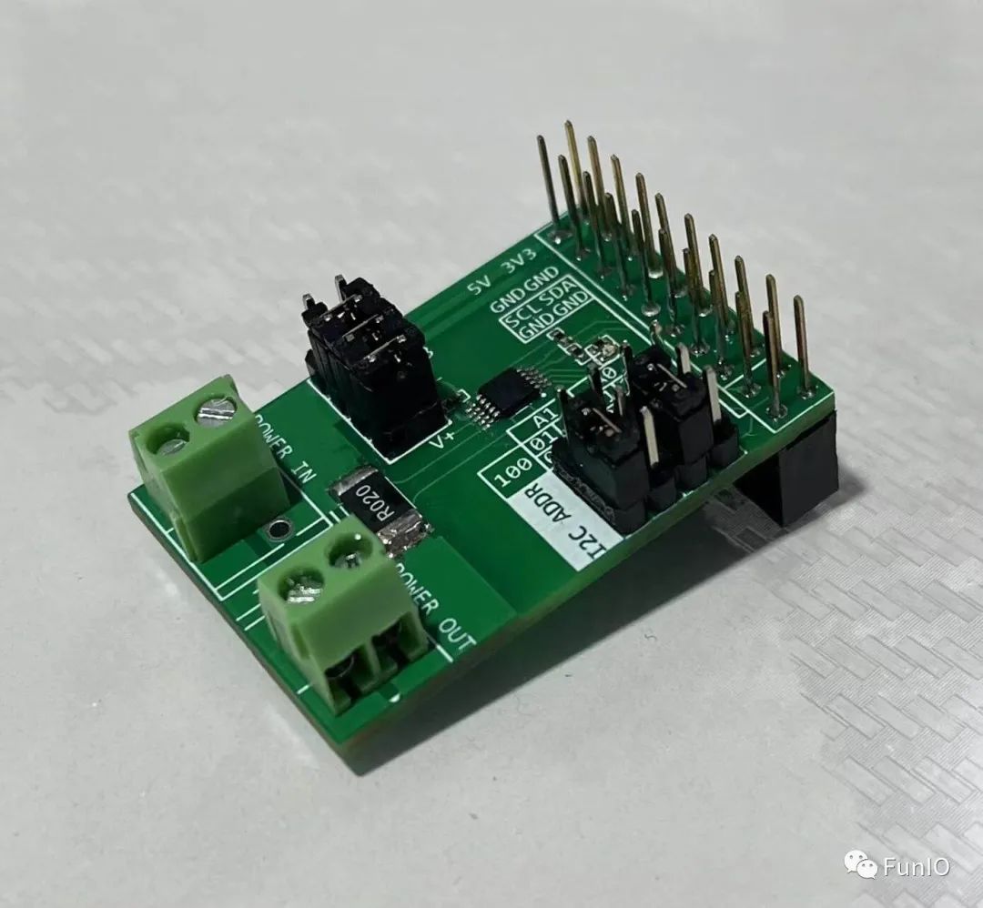
PCB
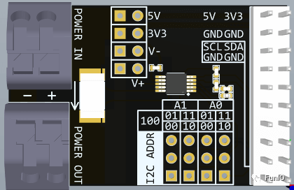
The samples have returned:
The project has been uploaded to GitHub:
https://github.com/pengwon/ina226
Testing
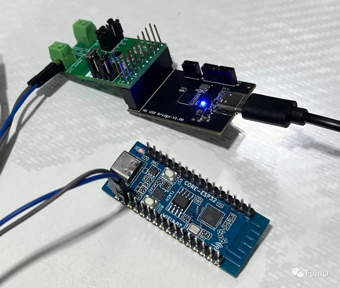
The Python API has been mostly written, testing it with the esp32-c3 module:
Test code:
sensor = INA226()
print(sensor.get_config())
sensor.set_alert_limit(0x1000)
print(sensor.get_calibration())
print(sensor.get_shunt_voltage(), 'uV')
print(sensor.get_bus_voltage(), 'mV')
print(sensor.get_current(), 'uA')
print(sensor.get_power(), 'mW')
sensor.set_mask_enable('SOL')
print(sensor.get_mask_enable())
sensor.close()
Output:
{'reset': False, 'avg': 0, 'vbus_ct': 4, 'vsh_ct': 4, 'mode': 7}
2048
595.0 uV
5035.0 mV
29750.0 uA
150.0 mW
{'SOL': True, 'SUL': False, 'BOL': False, 'BUL': False, 'POL': False, 'CNVR': False, 'AFF': False, 'CVRF': True, 'OVF': False, 'APOL': False, 'LEN': False}
This esp32 module has a program running, and the power consumption should be dynamically changing, let’s draw a dynamic graph:
In the future, I might have time to learn how to make a GUI, after all, aesthetics are justice.
References
CH347 High-Speed USB Bridge Module: https://github.com/pengwon/ch347-hs-usb-bridge