
MAKER: mosivers/Translator: Qun Endless
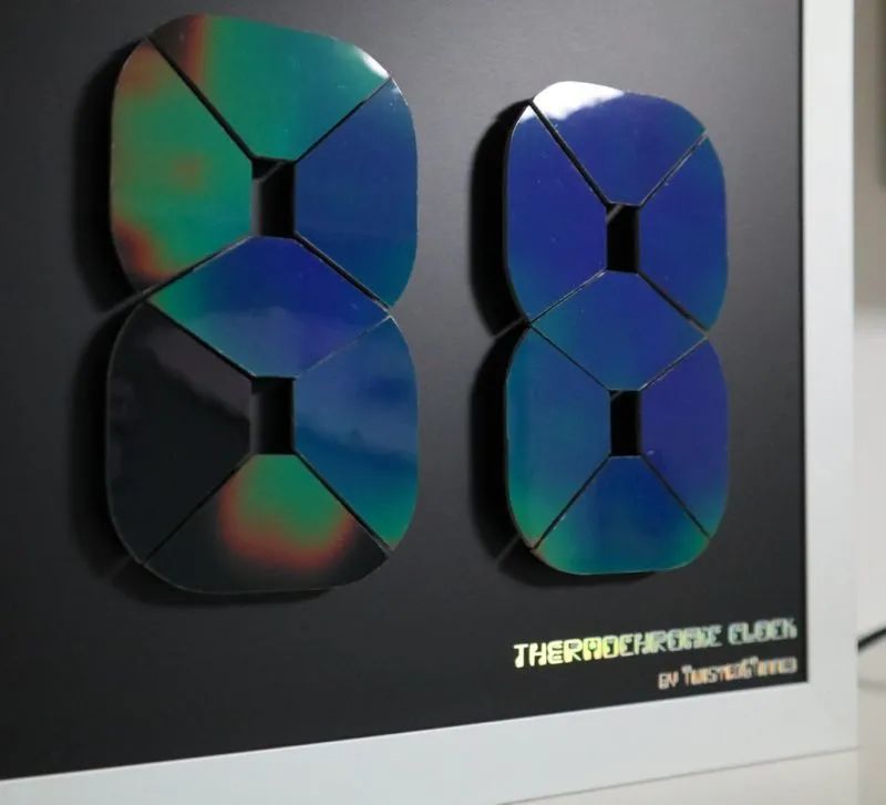
Thermochromic liquid crystal film is a fascinating material that changes color with temperature variations. DIYing a clock with this material makes the display and the changing process particularly unique!
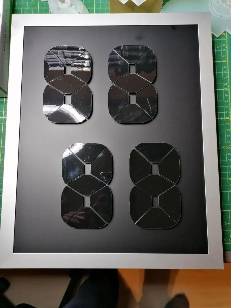
The clock uses a four-digit seven-segment display, with hours and minutes arranged vertically and slightly offset. Each part contains a controller PCB along with a thermochromic liquid crystal film, which changes color when the controller heats up.

Component List
Display segment PCB X 28 Controller PCB X 1350x450mm thermochromic liquid crystal film (30-35°C) X several 280x350x20mm aluminum outer frame X 1280x350x2mm black anodized aluminum plate X 15mm PCB spacers X 5630cm JST PH Dupont cables X 285V 5A power supply X 1 soldering iron X 1 hot glue gun X 1 utility knife X 1
Custom PCB
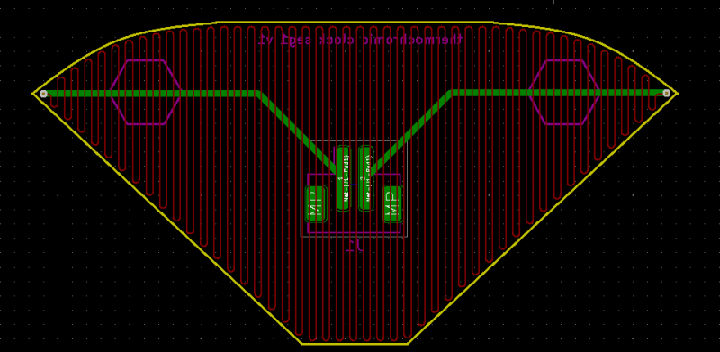
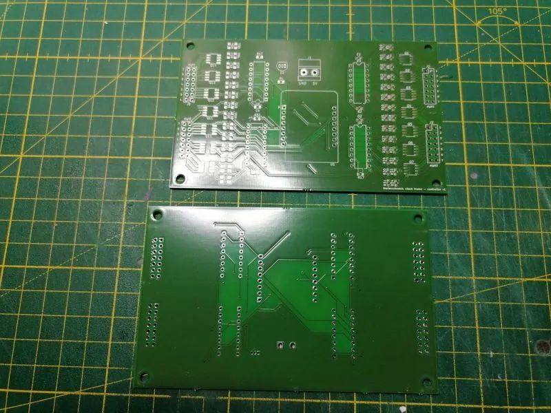
The display segment PCB is designed in KiCAD. It is a two-layer PCB, with heating wires on the top and a JST PH SMD connector on the bottom.
The bottom has silk-screen printed PCB spacers, which will later connect to the aluminum plate. I purchased a PCB with a black solder mask.
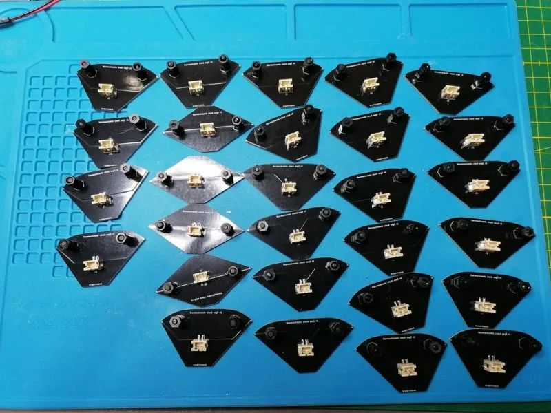
1. Use the soldering gun to connect to the connector.
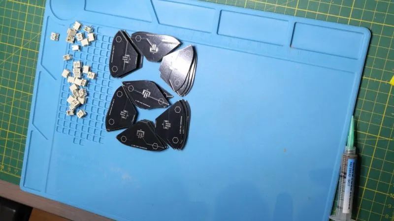
2. Use the hot glue gun to attach the two PCB brackets to the PCB.
3. Attach the thermochromic liquid crystal film to the top and use the utility knife to cut off the remaining foil.
The files for the custom PCB can be downloaded from the project repository: https://make.quwj.com/project/416
Controller PCB
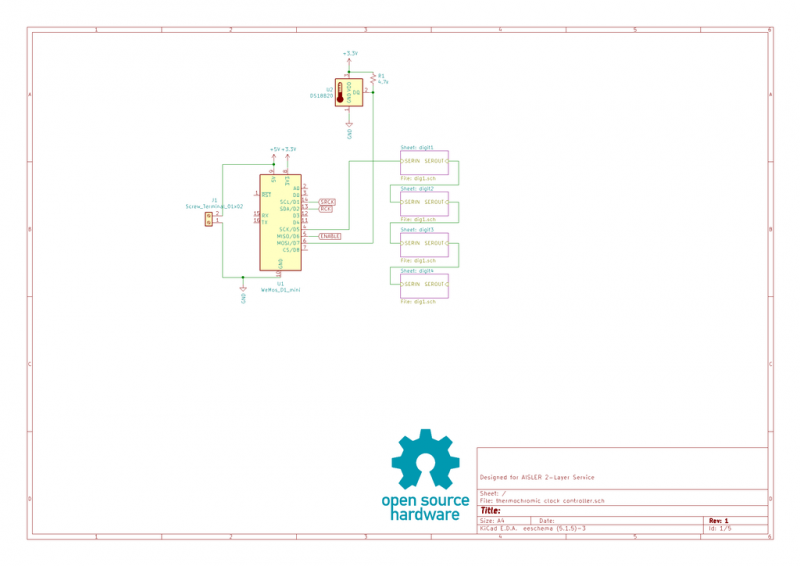
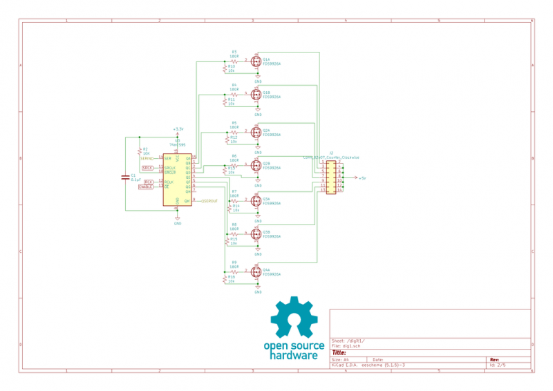
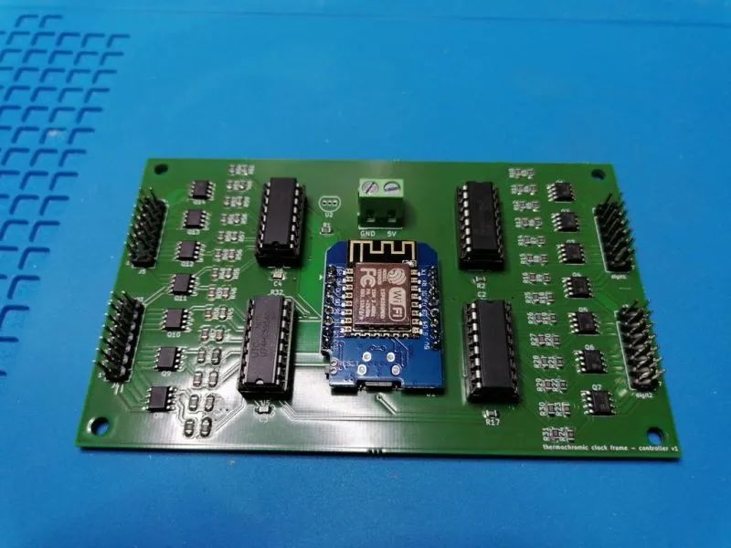
The controller PCB is also designed in KiCAD. It is based on the WEMOS D1 mini ESP8266 board and uses a 74HC595 shift register connected to n-channel MOSFETs for heating.
They are connected to the controller PCB via pin headers.
It also includes a DS18B20 temperature sensor to adjust heating power and time based on the ambient temperature.
The files for the controller PCB can be downloaded from the project repository: https://make.quwj.com/project/416
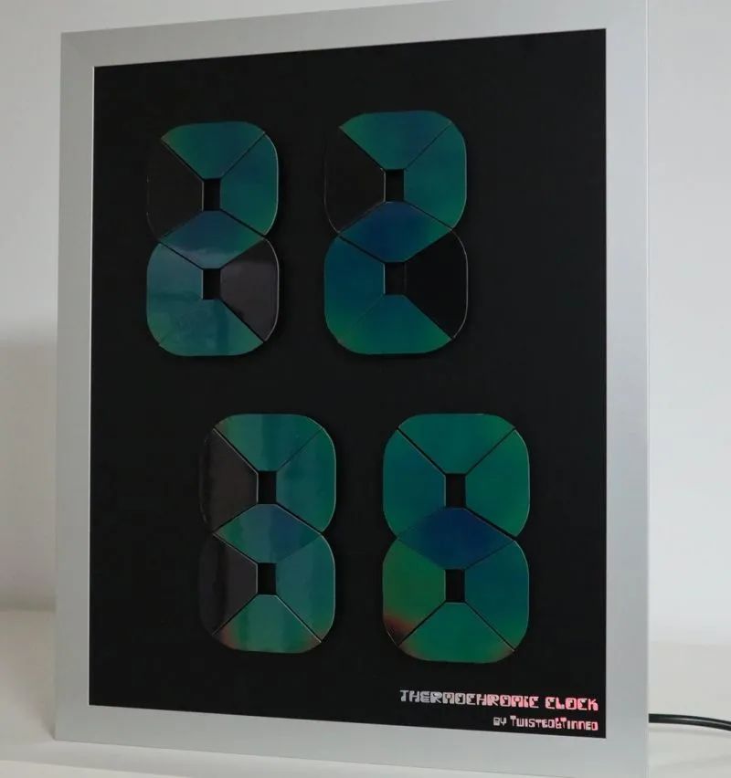
Clock Frame
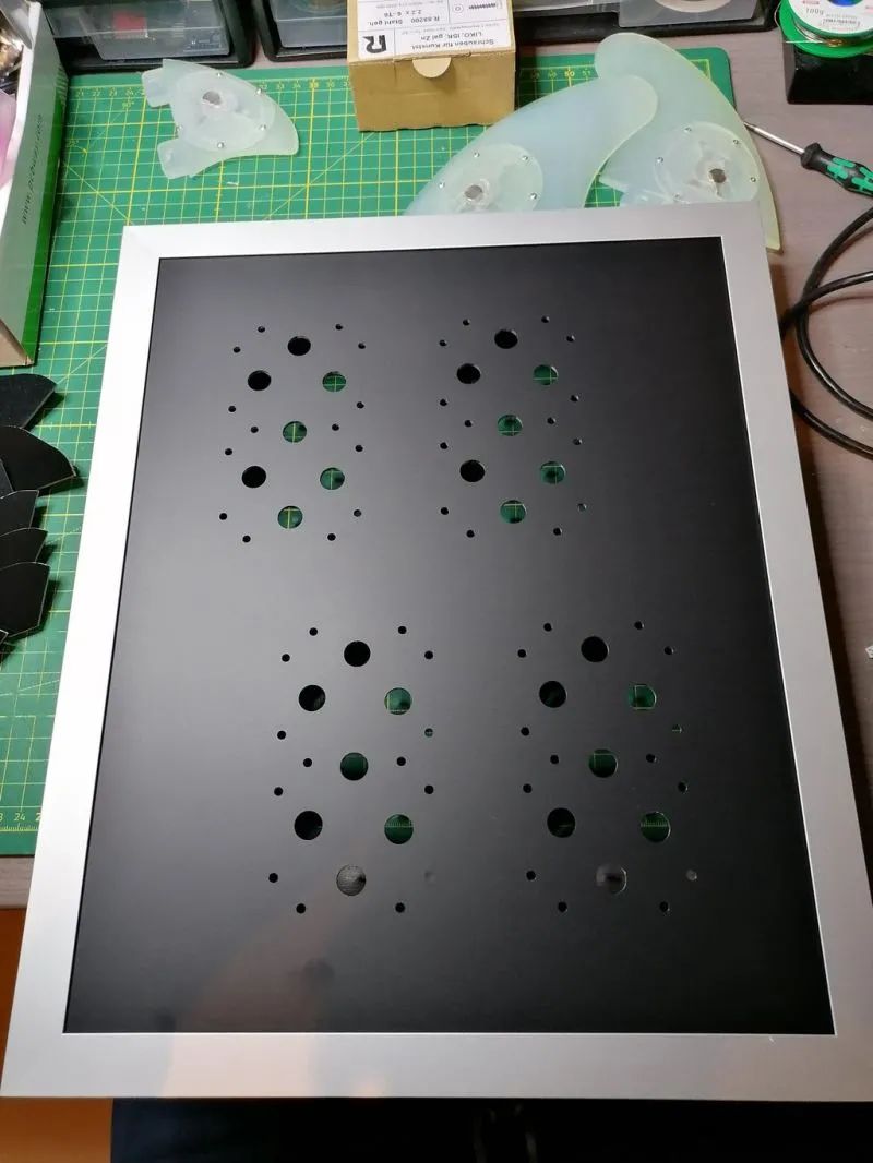
The clock uses a 280x350x20mm aluminum outer frame. This frame will connect to a black anodized aluminum custom board, and care should be taken during drilling to ensure alignment.
You may also consider using a 3D printed acrylic panel, approximately 2mm thick, which will have a more aesthetically pleasing overall look than the aluminum version.
The frame files can be downloaded from the project repository: https://make.quwj.com/project/416
Assembly
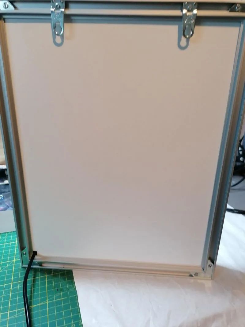
1. The overall frame is assembled from four aluminum pieces. Open one side, insert the front and back panels, and use the PCB brackets to secure these parts to the aluminum plate.
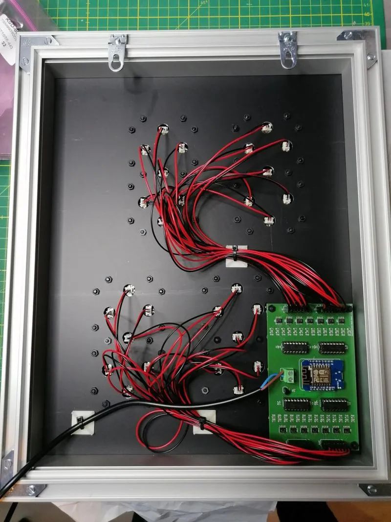
2. Connect the wires to each part. Use the PCB bracket to glue the controller PCB to the back of the aluminum plate.
3. Use zip ties to secure the wires, and make a hole in the back panel to pass the power cable through.
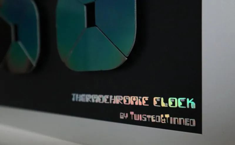
4. Add a personal mark at the bottom.
Code Principle Explanation
1. The ESP8266 fetches the current time from the NTP server and displays the time by heating the corresponding segments.
2. Each segment has a resistance of about 6 ohms, and when powered with 5V, each segment has a current of about 1A. To reduce total current consumption, each segment uses software PWM for heating. Next time, I will use a shift register with PWM capability (like PCA9685) to achieve this.
3. Achieving the right amount of heating power is not easy, as the duty cycle needs to be continuously adjusted based on the ambient temperature measured by the DS18B20. To ensure uniform heating across all segments, inactive segments will be heated with a higher duty cycle.
As seen in the video, the last digit cannot be clearly displayed because all segments take a considerable amount of time to reach thermal equilibrium. Currently, this version has a temperature sensor connected to each segment to maintain the same temperature consistently.
It can be concluded that the clock consumes a power greater than 3A, so a 5A power supply is used.
The code files can be downloaded from the project repository: https://make.quwj.com/project/416
Possible Improvements
 Once the coding part is completed, the clock will be finished.
In the future, I might make another version where each segment includes a temperature sensor. This would keep each segment flush with the front panel while covering it with a solid piece of liquid crystal film, but it would definitely lead to a “fading effect”.
via instructables.com/Thermochromic-Clock-Frame-Version/
The links in this article can be clicked at the end to read the original text

More Exciting Content