I have been thinking day and night about when I would start making a laser cutter. The amazing things that a real laser cutter can do constantly tease my imagination. One thing I have wanted to do for a long time is to build some model houses and other model railway scenery in my backyard, and maybe even make my own four-wheeled cart (at least a rough version). There are also other ideas, such as making attachments, signs, and engraved plates for my works, making paper cuts and stamps for my wife, and making dollhouses and furniture for my friends’ children… Oh, the mighty laser cutter!
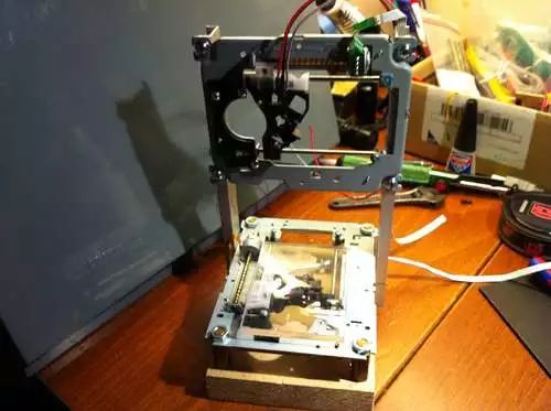
Now it’s time to share my latest project with everyone—a low-cost laser engraver, and through this project, I might have a chance to try out the real thing. Although the workspace is a bit small, it still works effectively, and the cost is very low, so most people can afford to make a copy.
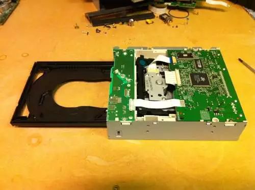
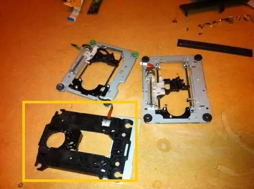
In the DVD-Rom drive, you only need the stepper motor components and the laser diode. I wasn’t very lucky and found that my DVD-Rom had a very difficult plastic component to deal with. So I disassembled three DVD-Rom drives but only used parts from two of them. The disassembly process is quite challenging, and most of the DVD-Rom drives I have opened are similar to this.
There is a small DC motor just below here, you can take it out for future projects
After removing the screws from the bottom of the drive, you can lift it off like a lid. You will likely see two circuit boards underneath the bottom cover, which are useless to us. But remember to keep other useful parts for other projects. For example, there is a small DC motor worth keeping under the front circuit board.
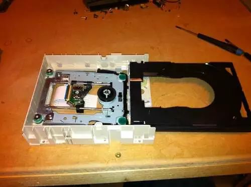
Now you should remove the front panel along with the front tray. After you pull out the tray, the front panel will become loose (just use a bobby pin and that small hole on the front panel).
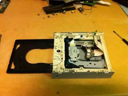
The next steps require removing screws, and maybe some brute force. Remove the two circuit boards. Be careful with the ribbon cable connected to the stepper motor.
This motor needs to be removed
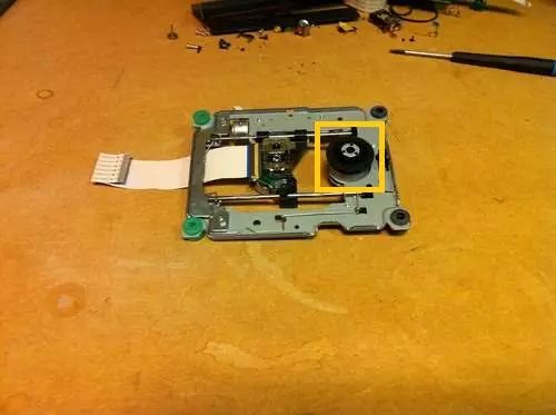
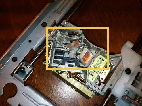
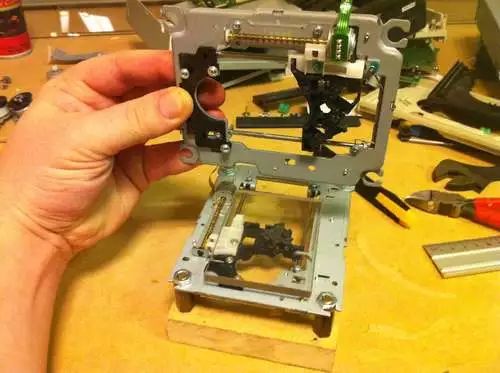
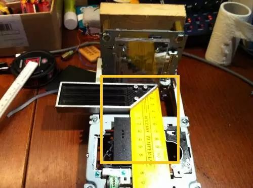
If you place the DVD-Rom drive with the right side up and remove the top cover, you should find what we are looking for—the stepper motor assembly. Unscrew it and take it out directly.
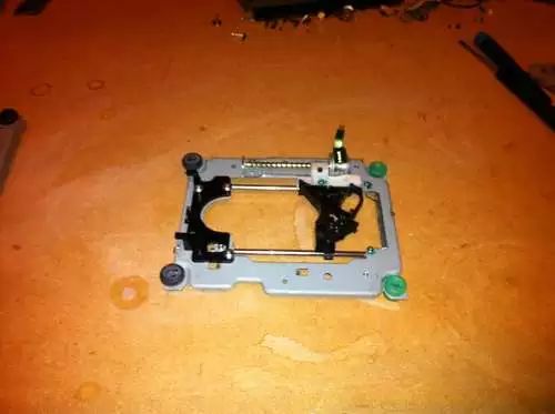
Now that we have removed the stepper motor assembly, we should do some cleaning. Remove the spindle motor; it might be useful, but I think it’s too troublesome to drive, so I discarded them. They are usually fixed with three very small screws, but sometimes they may be part of a larger component, so be careful not to damage the two rods supporting the lens.
The lens can be removed using the most suitable method; we need to leave a smooth surface to connect some other parts on it. Be careful not to damage the laser diode of the DVDR drive. If you don’t want to buy a new powerful laser emitter later, you have to treat this thing well.
This whole component needs to be removed and set aside for future projects
Laser diode
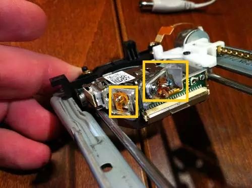
Removing the laser emitter from the DVDR drive is not difficult, but the shapes of most lens assemblies vary. Identify the laser diodes (there will be two, one infrared and one red) and remove them from the assembly.
These optical devices can be saved for future projects
There are two powerful magnets on each side of the lens, you deserve to have them
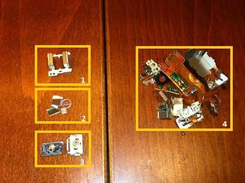
1. Magnets removed from the lens; 2. Mirrors and lenses; 3. Laser diodes; 4. Waste
Among these are some optical devices and two magnets; you can save them for future projects.

You need to remove the laser diode from the bracket. This requires a little gentle force. Be careful not to damage the laser diode
One is the infrared laser diode, and the other is the red laser diode we need
Remove the connecting circuit board from the diode
Once you have removed the two diodes, you must be very careful. These two diodes are very small and very fragile.
Remove that small piece of connecting circuit board from the diodes, and then check if the red laser diode is alive using two AA batteries.
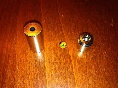
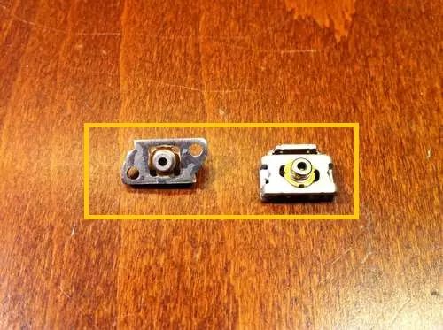
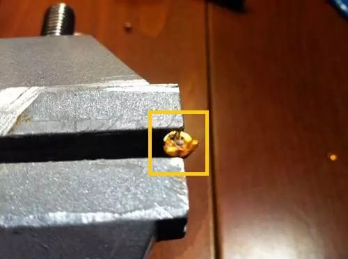
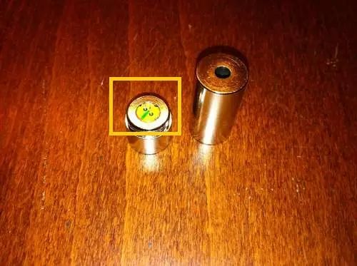
Now that you have the bare diodes, it’s time to install the diodes into the housing.
The small hole on the back of the laser emitter housing is just right for the diode leads to pass through
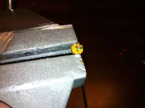
Place the diodes into the housing and carefully press them into the housing with the back of the housing and pliers.
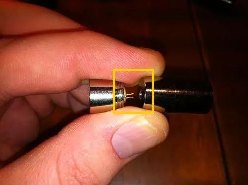
Now the diodes are securely placed in the housing
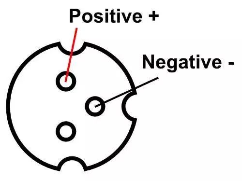
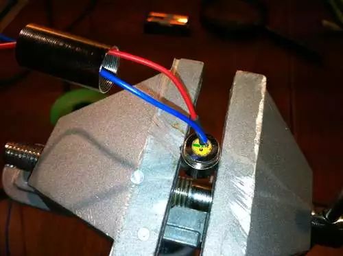
Once you complete this step, you will smoothly drive into the straight road before the finish line. Solder the wires to the positive and negative pins
Then screw the lens on, and you are done.
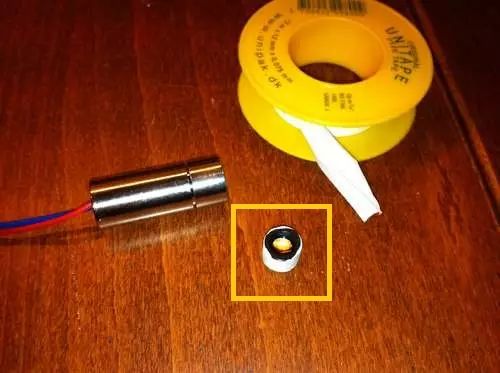
Use some Teflon tape to secure the lens in place
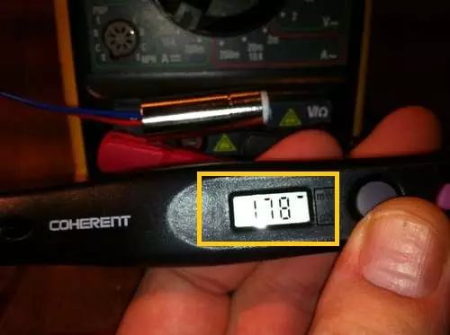
178 milliwatts of output power is quite good. However, it will put the diode into an overload state
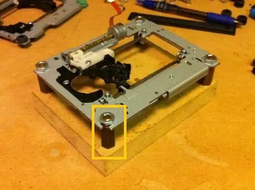
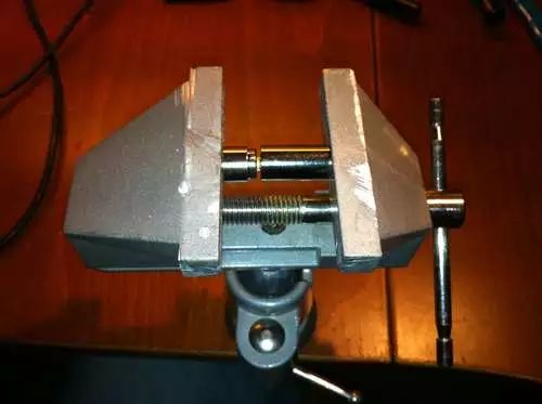
I was lucky to find these spacers, but a bolt and some nuts can also achieve a good effect
Using an acrylic sheet as the base
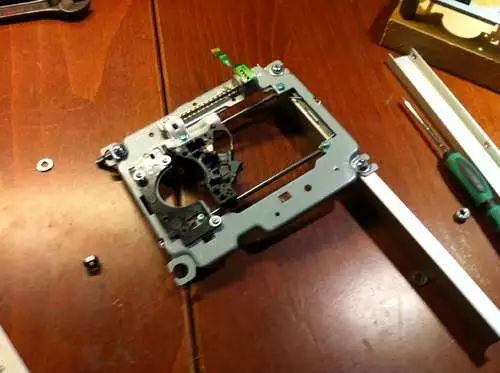
To keep it as simple as possible, I found a piece of medium-density fiberboard that is just slightly larger than the stepper motor assembly of the DVD-Rom drive. It will serve as the base and fix the X-axis and Y-axis directions.
I found some spacers to fix the Y-axis direction, but a few bolts and several nuts can also work well. The size requirements here are not strict, but it must ensure that each axis is perpendicular to the others. I found it easier to align the parts after installing the first layer of components on the medium-density fiberboard.
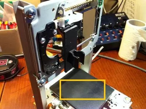
The workspace is located on the old laser diode assembly. Ensure it is placed flat and level, then apply some glue to secure it, and the workspace is complete. I found a 1/4 inch acrylic sheet to be just right. It provides enough stability for the workspace, but since the laser can penetrate it, I’m not sure if there are safety concerns. Later, I came up with what I think is the best solution. I cut a piece of metal casing from the DVDR drive that is the same size as the acrylic sheet and glued it on. This way, the workspace remains very stable, and the strength is sufficient. It also has the added benefit that you can use magnets to secure the items you want to engrave to the workspace.
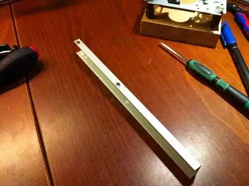
I found some aluminum profiles in the scrap box.
Used it as the X-axis, but you can use any sturdy and long material.
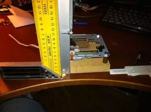
Measure what you think is the appropriate height for engraving.
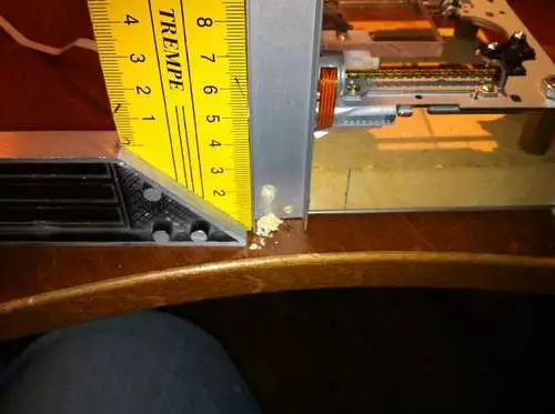
I chose several boards of 7.5 inches long as brackets. This leaves me with less than 2 inches of small gaps.
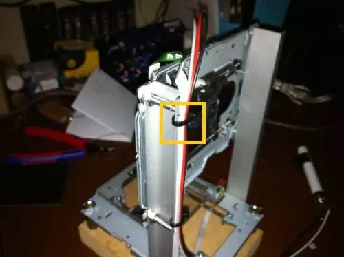
I drilled a few small holes so that I could tie the cables tightly with cable ties
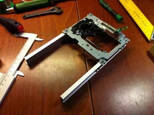
An important thing is that the mounting holes on the components are not symmetrical. Remember to measure the distance from the bottom of the bracket to the linear guide rail. This way, you can ensure that all parts align. The position of the X-axis installation depends on the position of the laser emitter. The laser emitter should be centered in the workspace, while the Y-axis should be in the middle. When you install the two axes on the base plate, first ensure that all parts are perpendicular to each other, and then drill a few small guide holes for the screws.
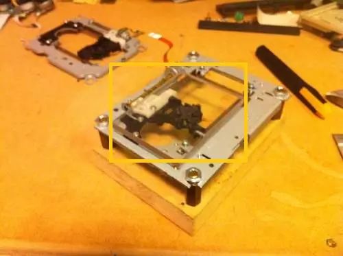
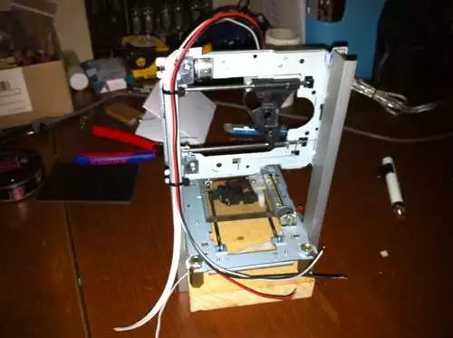
Now you should have completed the mutually perpendicular X-axis and Y-axis.
The most important size requirement here is to ensure that everything is square and at right angles
The bracket for the laser emitter does not have to be very complicated; I used a small piece of plastic and a clip, and then glued everything together.
Fix the laser emitter with a clip, so you can change the focus position simply by sliding the laser emitter up and down.
Like other parts, its size is not important, as long as everything is perpendicular to each other. There is only one size that you need to consider, which is the position of the laser emitter. When the Y-axis and X-axis are in the central position, it should be at the center of the workspace.
I tested it with a piece of black plastic the same as the laser emitter bracket. Finally, I tested it again with a piece of metal removed from the DVDR drive casing |
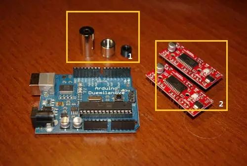
Electronic Components
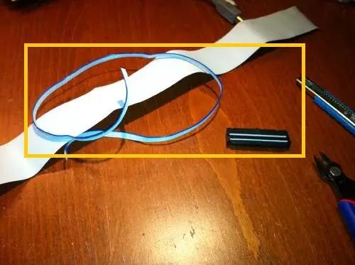
When looking for the necessary ribbon cables, old computers are your best choice
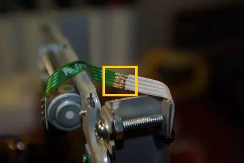
These ribbon cables are not easy to solder, but they work well. I did the same soldering on both stepper motors
I started soldering the stepper motors. Connect the stepper motor with a ribbon cable, and then solder them to the existing interface on the DVD circuit board. I soldered a four-pin plug on the other end, so it can be plugged into the test circuit board.
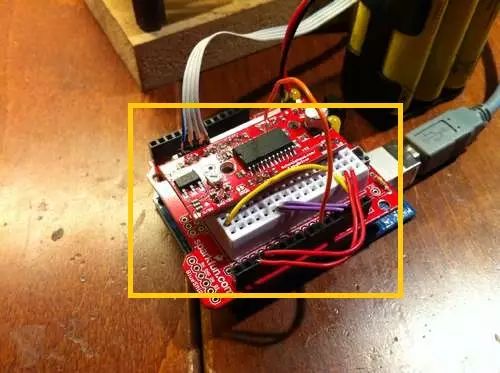
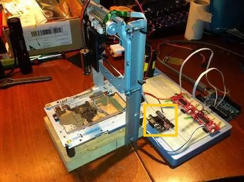
Initial testing of Easydriver and Arduino—big success
Do the same for the Easydriver, solder the pin plug, and then use it on the test circuit board.
Easydriver has two pins called MS1 and MS2, which are used to set the step sequence. Connect them both to the 5V output of the Easydriver. This sets the stepping sequence to micro-stepping control. Connect the four pins extending from the stepper motor to the motor output, while the control pins (step, dir, and gnd) connect to Arduino. Besides these, Easydriver also needs to connect to the motor power supply. I used a 12V power adapter to drive the motor, fan, and Arduino. A potentiometer is used to control the power to the motor; just set it to the lowest, and if the stepper motor is underpowered, adjust it a little higher. I am not sure about the rated voltage of the stepper motor; if they get hot, it indicates that the voltage you provided is too high.
Extra components that are not needed in this project
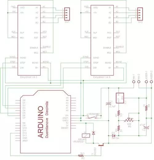
I added a relay to the circuit diagram for the fan. Because the engraving process produces some smoke, the fan is very useful.
The fan only needs to be connected to the fan output. A small computer fan works well; you just need to connect the positive and negative wires to the correct output.
Remember to check the positions for correctness when soldering all the pins
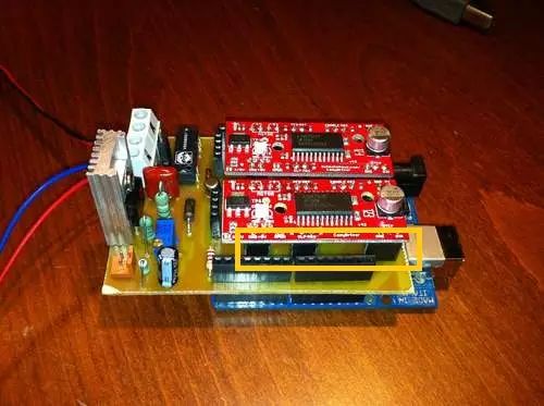
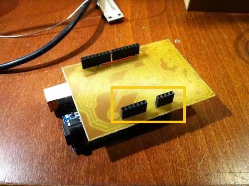
I installed the Easydrives in a socket, so they can be reused in future versions
When you put the Easydrivers into a box, you need a fan to cool them down. They can get crazy hot
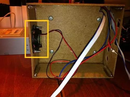
To improve this small engraving machine, I made a small box from Masonite fiberboard removed from a picture frame. Just glue it together.
There is a small fan removed from an old graphics card in front. When you put the Easydrivers into any enclosure, you need to cool them. They get hot when they are bare, and even hotter when placed in an enclosure.
Gluing some spacers can make it easier to secure with screws on the bottom cover
I glued some threaded spacers inside the box so that I can screw in screws from the bottom.
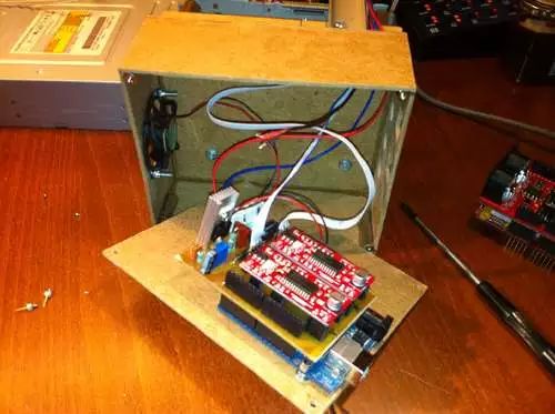
Screw the Arduino upside down to the bottom. This way, the engraving machine becomes a convenient and useful tool.
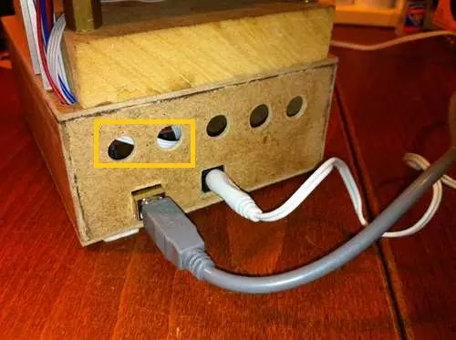
Ventilation holes
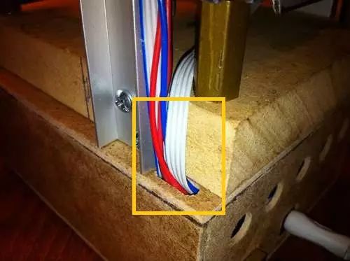
All wires entering the box pass through the top
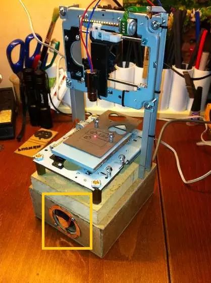
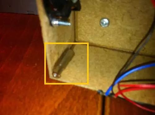
I found this fan guard intact from an old graphics card
This is a 40mm computer fan, connected to the relay of the laser emitter. The fan faces outward from the workspace, gently sucking away the smoke.
Connect the fan to the relay of the laser emitter, facing outward from the workspace. It can suck away smoke without affecting the devices in the workspace
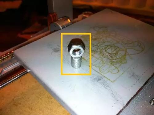
Glue a nut on top of the neodymium magnet. It holds your workpiece well
Another small but useful additional part is the magnets used to hold paper and other lightweight objects. I found these magnets from an old toy. Just glue some nuts on top, and you’re done.
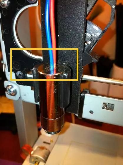
When the laser emitter is at its lowest position, the focus should align with the surface of the workspace
To change the focus, you need to adjust the lens by turning a screw. Alternatively, you can set the focus on the workspace first, then slide the laser emitter up and down on the bracket.
When the laser emitter is at its lowest position on the bracket, I fix its focus. Then all I need to do is measure the thickness of the workpiece and raise the laser emitter the same height. In most cases, I just need to place the workpiece next to the laser emitter bracket and move the laser emitter to the correct height.
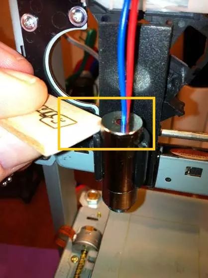
When I move the laser emitter to the same height as the workpiece, the focus is adjusted to the top of the workpiece
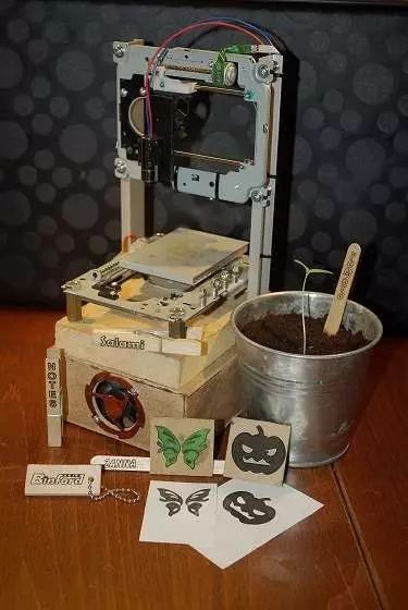
Here are the items I have made with the engraving machine so far, and I will try to showcase them with pictures. Imagination is the only limit (aside from the low power of the engraving machine and the small size of the workspace).
Keychain
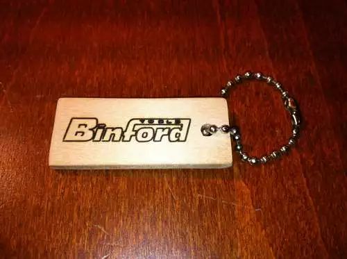
I love the classic “Home improvement” TV show. Why not make a Binford keychain?
I found some paint stirrers at my local DIY store. I love the look of these wooden sticks, and they are not expensive. I sawed one off and drilled a small hole. After some sanding, I engraved the Binford logo from the sitcom “Home Improvement” on it.
Plant Tags
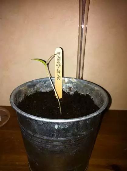
Engraving the names of plants on ordinary popsicle sticks.
The text is less than 2mm high and barely legible, but the photos don’t come out very clearly.
Personalized Matches
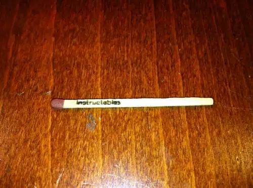
I’m just showing off~
Memo Pad
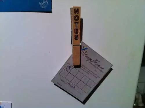
Engraving on clothespins, then gluing a small neodymium magnet on the back can hold a memo pad on the fridge or other metal surfaces very well.
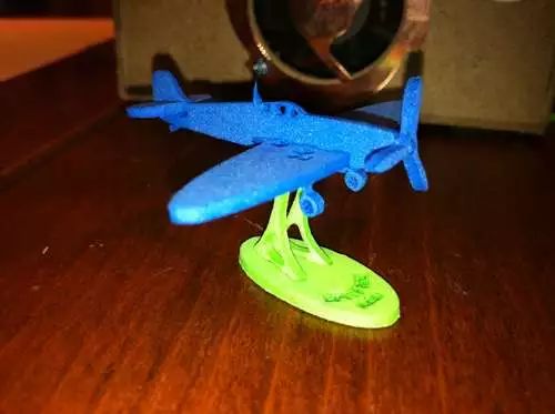
Airplane
For questions about the program, please click on the link below Read the Original to browse
Image source: 123rf.com.cn copyright image library

Guokr Space and Guokr Lab have joined forces to form Guokr Innovation Space! Here, entrepreneurial teams can enjoy evaluation reports provided by Guokr Lab and receive advice from makers; makers can also provide your creative ideas here, and we will realize them together! In addition, there are more interesting online and offline activities waiting for your participation, exciting content, jointly presented.
Copyright of this article belongs to Guokr, reproduction is not allowed
If you need to contact us: [email protected]