
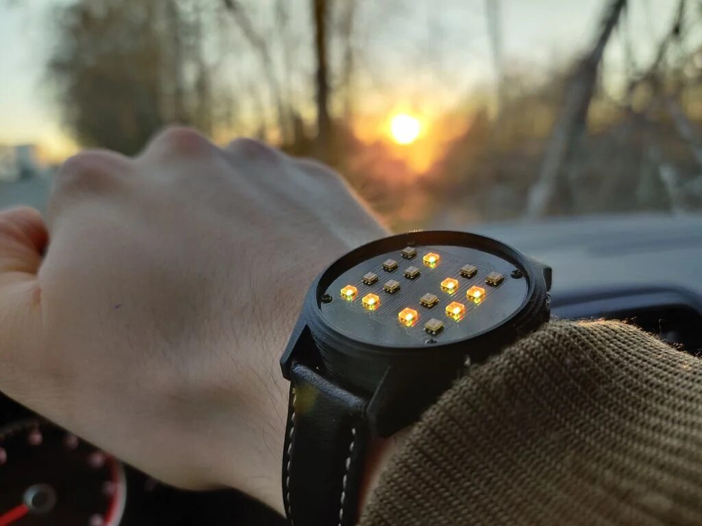
As shown in the picture, today I will introduce a cool project – a binary watch full of electronic style, made by Swedish electronics enthusiast Alex. This project won first place in the watch category competition on instructables.
Note: For codes and materials mentioned in the text, you can click the lower left corner “Read the original” or reply “Alex Binary Watch” in the backend to get.
Main Project Text
Recently, I started to learn some knowledge about binary watches, and I began to search for relevant materials to see if I could make one myself.However, I found it difficult to find a design that is both practical and stylish, so in a fit of frustration, I decided to simply design one from scratch myself.
Creativity
The inspiration comes from the video below:
The first step to making a binary watch is to establish some design standards, and I thought of the following:
Establish Design Standards
-
Support binary RGB display mode -
Support time display (very precise timing) -
Support date display -
Support stopwatch function -
Support alarm function -
Long battery life -
Support USB charging -
Software customizable by users -
Simple and clean design
These standards became the basis for the entire project design. The next step will clarify how I want the watch to work.
Step 2: Simple Theory of Binary Presentation
The plan is simple.The binary watch will work like a regular watch, except the interface will be binary display.
This uses BCD code.
BCD Code (Binary-Coded Decimal)
Using 4 bits of binary numbers to represent 1 decimal digit from 0 to 9, it is a form of binary numerical coding, using binary encoded decimal codes.
This coding form of BCD utilizes four bits to store a decimal digit, allowing for quick conversion between binary and decimal.
The 8421 BCD code is the most basic and commonly used BCD code, which is similar to the four-bit natural binary code, with weights of 8, 4, 2, and 1, also known as weighted BCD code.
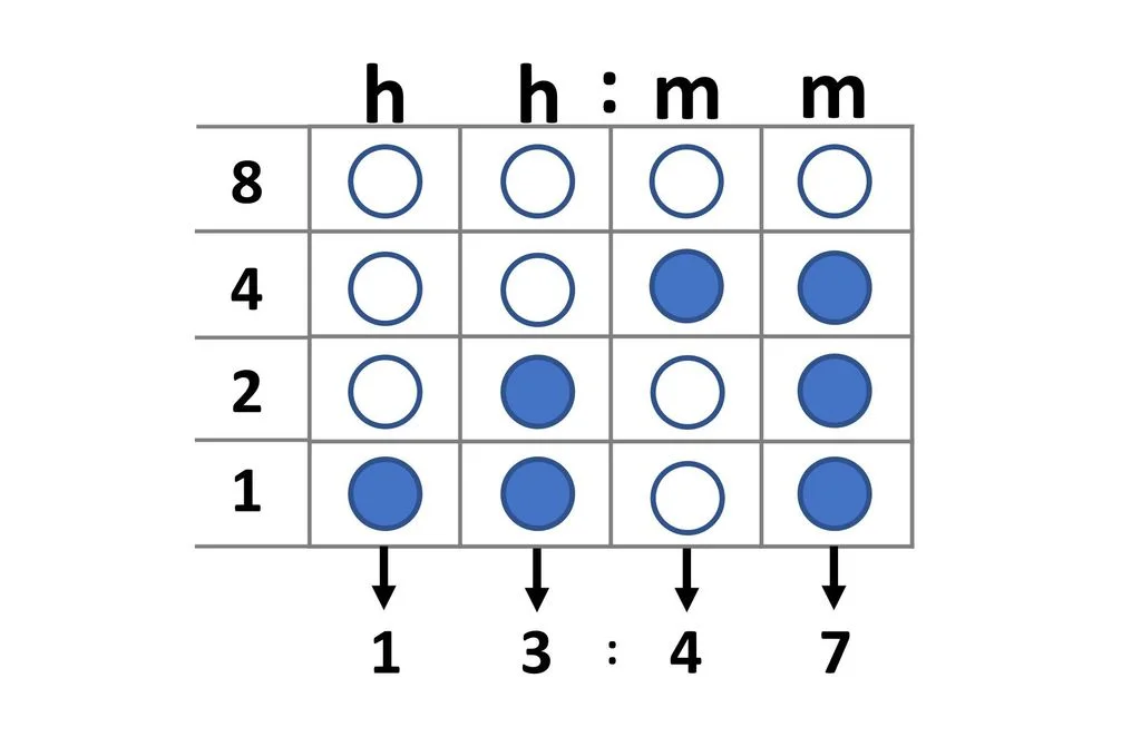
I need to use 4 bits to represent numbers from 0-9. And for the standard HH:MM time format, I need four such digits. This means a total of 16 bits, represented by 16 LEDs.
Once you get used to reading time in BCD, it becomes quite easy.
The bottom row of the watch represents the least significant bit (1), and the top row represents the most significant bit (8). Each column represents a digit in the HH:MM time format. If the LED is lit, the value is counted. If the LED is off, it is ignored.
To read the first digit, simply add up the values of all the lit LEDs in the first (leftmost) column. Do the same for the other digits from left to right.
So the time displayed above corresponds to 13:47!
This principle applies to other functions of the watch as well.
The reason for using RGB LEDs is to help distinguish different functions and modes using different colors. This allows users to easily browse these functions without confusion.
Next, let’s create the block diagram.
Step 3: Start Working
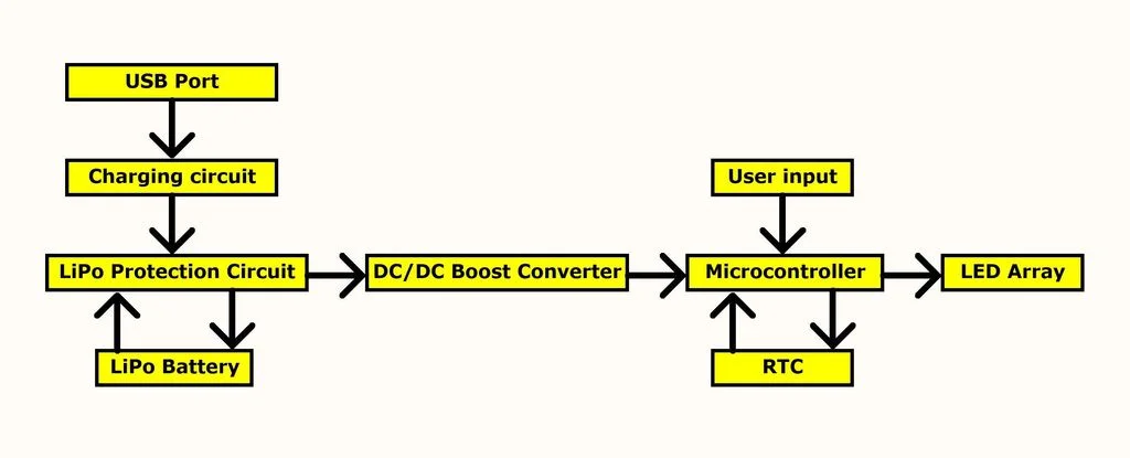
Like any other electronic project, the block diagram is an important part of the early design phase.
Based on these standards, I managed to organize the above block diagram. Each box in the diagram represents a function in the circuit, and the arrows indicate the relationships between these functions. The entire block diagram outlines how the circuit works.
The next step is to start making decisions about the components of each module in the block diagram!
Step 4: Choose Components
This circuit has quite a few components. Below, I will pick some of the most important parts to explain why I chose them.
LED
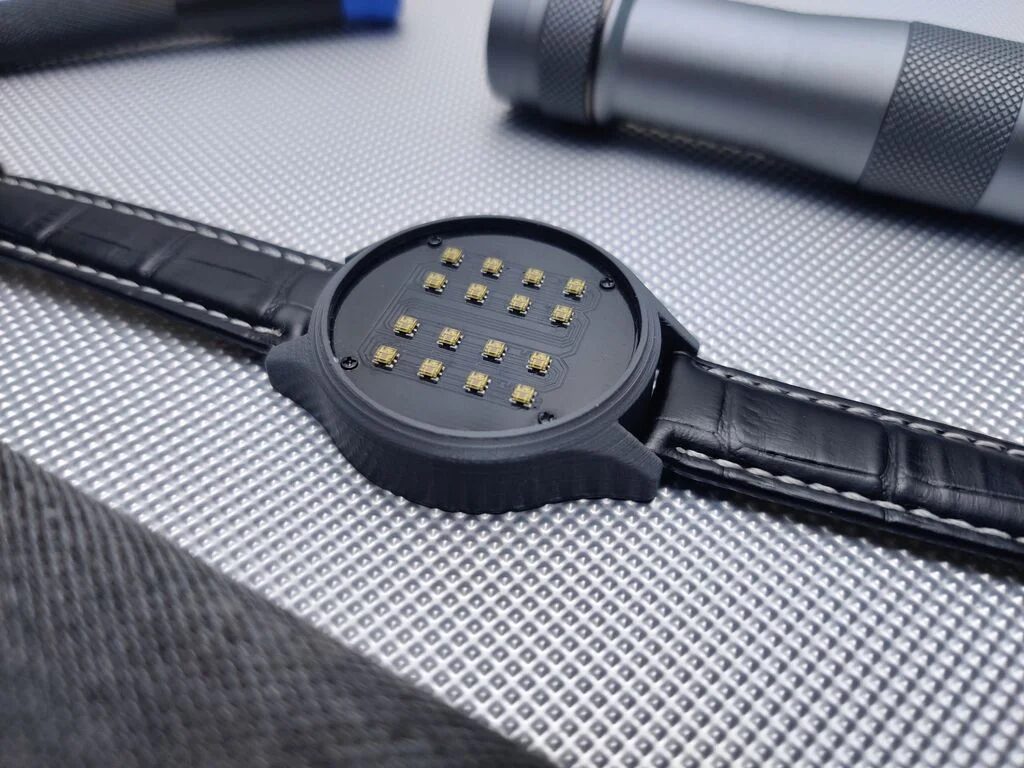
For the binary display interface, the choice is quite simple. I knew I wanted to use LEDs for display and found that I needed 16 LEDs (in a 4×4 grid) to display as much information as possible.
In my search for LEDs that would perfectly present, the APA102 came up. It is a very small (2mm X 2mm) addressable LED with a wide range of colors and is quite cheap. Although I had never worked with them before, they seemed very suitable for this project, so I decided to use them.
Microcontroller
The choice of microcontroller was also simple.
I have extensive experience with the ATmega328P-AU and am familiar with its functions.
This is the same microcontroller used on the Arduino Nano board.
I know there are cheaper microcontrollers, but since the Atmega328 fully supports all Arduino libraries, this was also an important factor in choosing it for this project.
RTC (Real-Time Clock)
The main requirement for the RTC is accuracy. Considering that the watch is not connected to the internet and cannot be recalibrated through an internet connection, the user needs to calibrate it manually, so I wanted the watch’s timing to be as accurate as possible.
The M41T62 RTC is the highest precision I could find (±2ppm, equivalent to ±5 seconds per month). Combining high precision with I2C compatibility and extremely low current consumption makes this RTC an ideal choice for our project.
DC-DC Boost Converter
When choosing the DC-DC boost converter IC, I just had to look at the circuit and determine the required voltage and current. Running the circuit at low voltage reduces current consumption, but it cannot be lower than 4.5V (the minimum microcontroller voltage at 16MHz clock frequency), and it cannot be higher than 4.5V (the maximum voltage for the RTC). This means the circuit must operate at a precise 4.5V voltage.
Through calculations, the maximum current of the circuit will not exceed 250mA. Therefore, I started looking for a boost converter that could meet the requirements and soon discovered the TPS61220.
The TPS61220 requires very few external components, is quite cheap, and can meet the current and voltage requirements.
Battery
The main requirement for the battery is size. The battery must be small enough to fit in the watch case, or else the watch will look bulky.
I calculated that the battery size should not exceed 20mm×35mm×10mm.
Due to size constraints and the 250mA current requirement, my choice of battery was limited to lithium batteries.
I found the