To avoid missing my updates, remember to check the public account in the upper right corner and set it as a star, take down the stars and give them to me.

Today, I will share a LoRa project demonstrating how to use the RYLR896 LoRa module with real-time feedback to create a LoRa Arduino ESP8266 setup for remote control of a relay. Below is the tutorial and demonstration for the project —
The video above mainly covers the following content:
-
ESP8266 Arduino LoRa home automation project;
-
Composition of transmitter and receiver LoRa circuits;
-
How to configure LoRa using AT commands;
-
Introduction to the project’s source code;
-
How to connect the LoRa module with Arduino and ESP8266;
-
How to control high-voltage appliances using LoRa.
Follow all the steps below, and you can easily create this LoRa Arduino project to control any device. Especially useful in remote areas without Wifi and Bluetooth, this can achieve control from up to 10 kilometers away. Of course, LoRa, as a low-power wireless standard, can transmit further than other wireless methods under the same power conditions, achieving a balance between low power consumption and long range, giving it a place in the Internet of Things. If you are interested in LoRa, this project can help you practice.
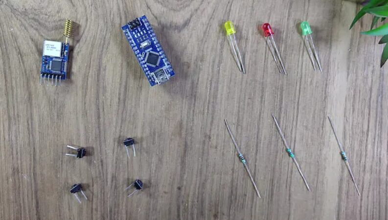
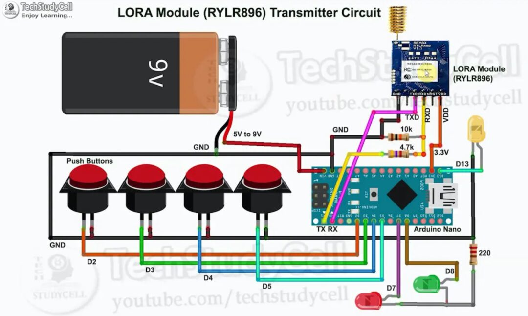
Components required for the transmitter circuit:
-
RYLR896 LoRa module
-
Arduino Nano
-
220Ω, 4.7K, 10K resistors
-
LED
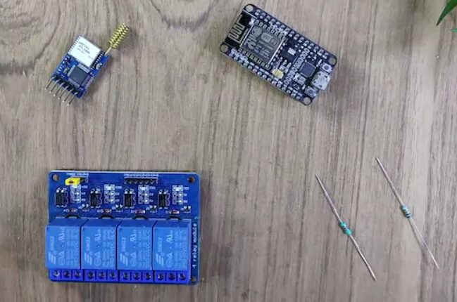
Components required for the receiver circuit:
-
RYLR896 LoRa module -
ESP8266 Node processor -
5V 4-channel relay module -
4.7k, 10k resistors
Components required on the receiver circuit PCB:
1. 5V relay (single pole double throw)
2. BC547 transistor
3. PC817 optocouplers
4. 510Ω 0.25w resistors (R1 – R4)
5. 1k 0.25w resistors (R5 – R9)
6. 5mm LED
7. 1N4007 diodes (D1 – D5)
8. Switch button
9. Terminal connectors
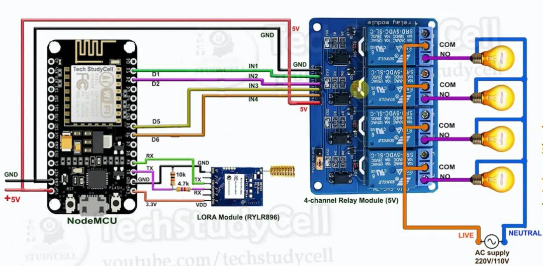
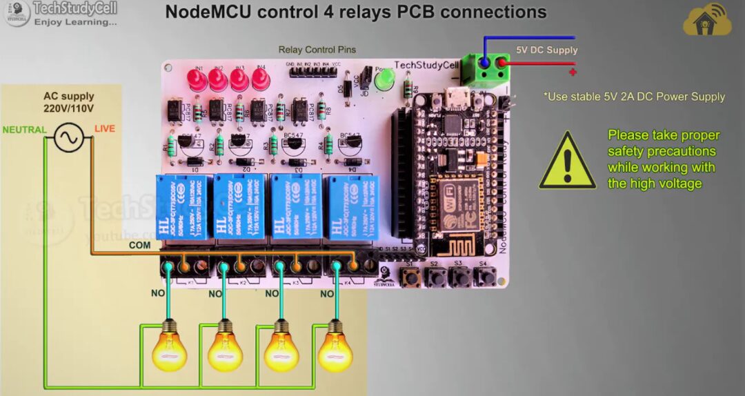
Receiver LoRa circuit using NodeMCU
Using AT commands to configure parameters
AT+ADDRESS=1AT+NETWORKID=5AT+BAND=865000000AT+ADDRESS=1AT+NETWORKID=5AT+BAND=865000000Code for the LoRa project using Arduino and ESP8266
Transmitter code:
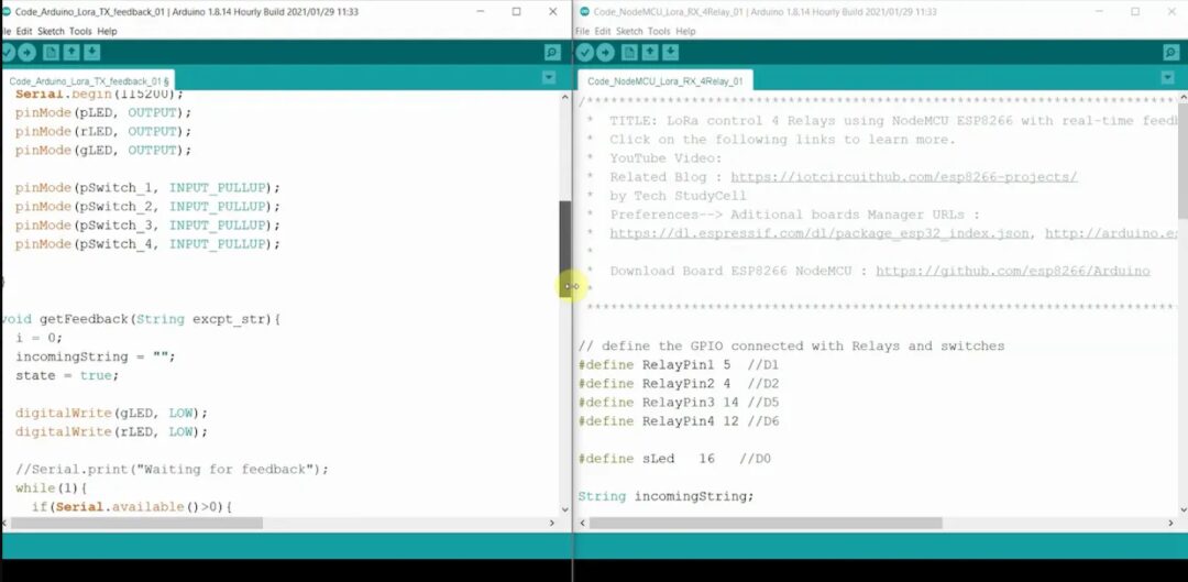
/************************************************************************************************************************************************* * TITLE: This is transmitter LoRa Arduino sketch to send and receive signal * Click on the following links to learn more. * YouTube Video: https://youtu.be/uWCY1CkvhR8 * Related Blog : https://iotcircuithub.com/esp8266-projects/ * by Tech StudyCell *************************************************************************************************************************************************/const int pLED = 13;const int rLED = 7;const int gLED = 8;const int pSwitch_1 = 2;const int pSwitch_2 = 3;const int pSwitch_3 = 4;const int pSwitch_4 = 5;int i;String incomingString;boolean state;void setup() { // put your setup code here, to run once: Serial.begin(115200); pinMode(pLED, OUTPUT); pinMode(rLED, OUTPUT); pinMode(gLED, OUTPUT); pinMode(pSwitch_1, INPUT_PULLUP); pinMode(pSwitch_2, INPUT_PULLUP); pinMode(pSwitch_3, INPUT_PULLUP); pinMode(pSwitch_4, INPUT_PULLUP);}void getFeedback(String excpt_str){ i = 0; incomingString = ""; state = true; digitalWrite(gLED, LOW); digitalWrite(rLED, LOW); //Serial.print("Waiting for feedback"); while(1){ if(Serial.available()>0){ incomingString = Serial.readString(); if(incomingString.indexOf(excpt_str) > 0) { state = true; break; } } if (i > 60) { state = false; break; } delay(100); digitalWrite(pLED, !digitalRead(pLED)); i++; } if(state){ digitalWrite(gLED, HIGH); digitalWrite(rLED, LOW); digitalWrite(pLED, LOW); //Serial.println("Received"); } else{ digitalWrite(gLED, LOW); digitalWrite(rLED, HIGH); digitalWrite(pLED, LOW); //Serial.println("Not Received"); }}void loop() { // put your main code here, to run repeatedly: if (digitalRead(pSwitch_1) == LOW){ Serial.println("AT+SEND=2,6,R1"); getFeedback("FR1"); } else if (digitalRead(pSwitch_2) == LOW){ Serial.println("AT+SEND=2,6,R2"); getFeedback("FR2"); } else if (digitalRead(pSwitch_3) == LOW){ Serial.println("AT+SEND=2,6,R3"); getFeedback("FR3"); } else if (digitalRead(pSwitch_4) == LOW){ Serial.println("AT+SEND=2,6,R4"); getFeedback("FR4"); }} Receiver code:
/********************************************************************************** * TITLE: LoRa control 4 Relays using NodeMCU ESP8266 with real-time feedback (Receiving end) * Click on the following links to learn more. * YouTube Video: https://youtu.be/uWCY1CkvhR8 * Related Blog : https://iotcircuithub.com/esp8266-projects/ * by Tech StudyCell * Preferences--> Aditional boards Manager URLs : * https://dl.espressif.com/dl/package_esp32_index.json, http://arduino.esp8266.com/stable/package_esp8266com_index.json * Download Board ESP8266 NodeMCU : https://github.com/esp8266/Arduino * **********************************************************************************/ // define the GPIO connected with Relays and switches#define RelayPin1 5 //D1#define RelayPin2 4 //D2#define RelayPin3 14 //D5#define RelayPin4 12 //D6#define sLed 16 //D0String incomingString;void setup(){ Serial.begin(115200); pinMode(RelayPin1, OUTPUT); pinMode(RelayPin2, OUTPUT); pinMode(RelayPin3, OUTPUT); pinMode(RelayPin4, OUTPUT); pinMode(sLed, OUTPUT); //During Starting all Relays should TURN OFF digitalWrite(RelayPin1, HIGH); digitalWrite(RelayPin2, HIGH); digitalWrite(RelayPin3, HIGH); digitalWrite(RelayPin4, HIGH); digitalWrite(sLed, HIGH);}void loop(){ lora_control();}void lora_control(){ if(Serial.available()) { incomingString = Serial.readString(); digitalWrite(sLed, LOW); if(incomingString.indexOf("R1") >0) { digitalWrite(RelayPin1, !digitalRead(RelayPin1)); Serial.println("AT+SEND=1,6,FR1"); } else if(incomingString.indexOf("R2") >0) { digitalWrite(RelayPin2, !digitalRead(RelayPin2)); Serial.println("AT+SEND=1,6,FR2"); } else if(incomingString.indexOf("R3") >0) { digitalWrite(RelayPin3, !digitalRead(RelayPin3)); Serial.println("AT+SEND=1,6,FR3"); } else if(incomingString.indexOf("R4") >0) { digitalWrite(RelayPin4, !digitalRead(RelayPin4)); Serial.println("AT+SEND=1,6,FR4"); } delay(100); digitalWrite(sLed, HIGH); }}PCB designed for receiving LoRa circuit
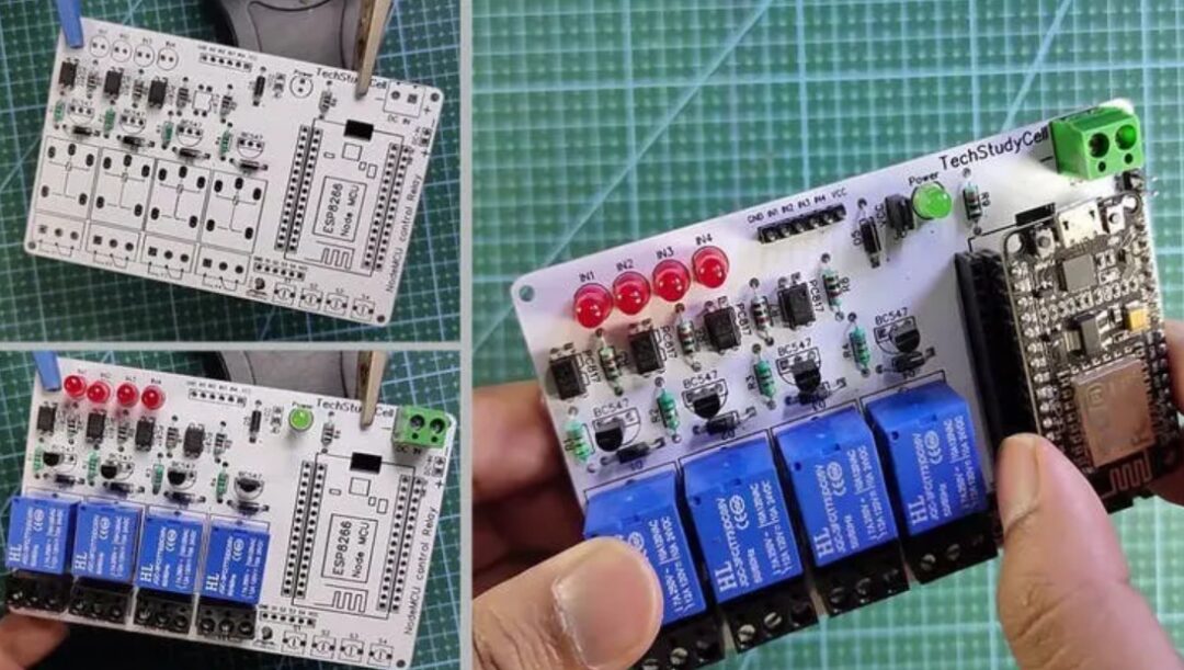
To make the circuit compact and professional-looking, a PCB was designed after testing all functions of the smart relay module. You can download the Gerber files for this home automation project PCB from the following link:
Afterward, I soldered all components according to the circuit diagram.
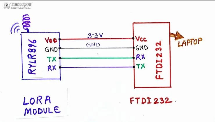
Connecting the LoRa module with Arduino and ESP8266
Original link:
https://www.hackster.io/techstudycell/lora-project-with-esp8266-arduino-control-relay-70c56b