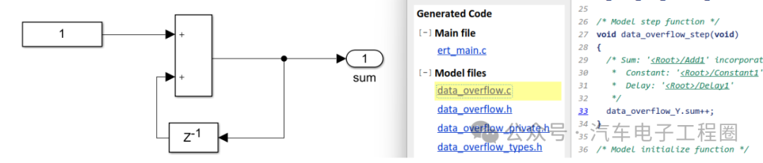
During the development of the ASW model for automotive ECUs, the toolchain and development environment are usually configured at the early stages of the project. For instance, in the Simulink model library, even the simplest operators, such as Add, are configured to standardize the usage of various Simulink blocks among team members.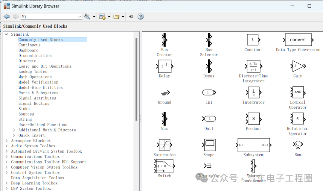 As a team member, one might only use these modules without paying much attention to whether any configurations have been made, as long as everything functions normally. However, neglecting these details can lead to common errors, such as the frequently encountered data overflow issue. Sometimes, one might assume that Simulink’s automatic code generation includes an overflow mechanism, but this is not the case. Instead, it is the configuration of the addition module that generates the data overflow handling mechanism.1 Data Overflow Handling in the Add ModuleWhen we add an addition module without any configuration and perform an accumulation operation, if the data type is defined as uint8, it means the value range is 0-255. Starting from 0+1 and continuously accumulating, when we reach 255+1, the result will be 0 due to data overflow.
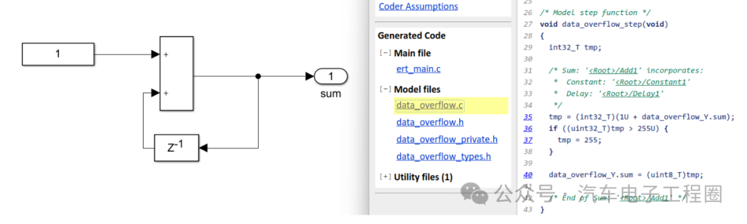
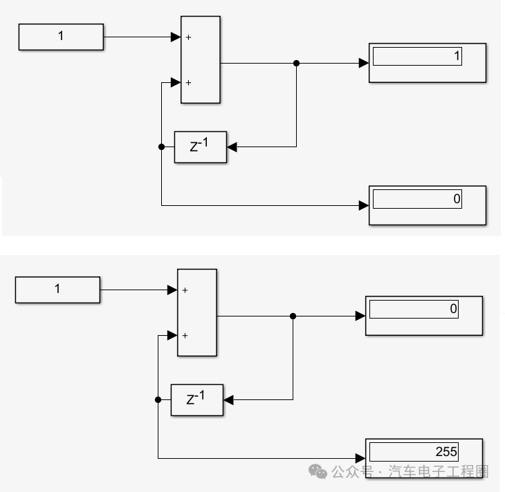 However, if we configure the addition module to prevent data overflow and then perform this accumulation operation, when we reach 255+1, the result will be capped at 255, as shown below:
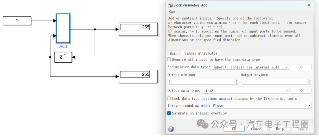
 The configuration for data overflow is specifically found on the signal properties page of the addition module, where you can check the option for Saturate on integer overflow, as shown in the image below:
 We can also observe this through the generated code. If the accumulation result exceeds 255, it will be capped at 255.
 If we do not check the option forSaturate on integer overflow, then accumulation will lead to data overflow, which can be clearly seen in the generated code, as shown below:
 This type of data overflow is not permissible, similar to division by zero. Such errors can directly lead to severe impacts on vehicle functionality and performance. According to reports, the following failure cases have been observed:
- Data overflow can overwrite real-time control parameters in the ECU memory, such as incorrect fuel injection correction factors or ignition advance angle mapping tables, resulting in torque fluctuations of ±15% under low-speed conditions.
- Division by zero errors can directly cause critical algorithms to crash (for example, if the transmission control module encounters a division by zero exception while calculating the shift curve, it may skip the shift logic judgment, leading to power interruption or abnormal jerking).
- If the ABS control unit modifies the wheel speed sensor calibration values due to data overflow errors, it may lead to abnormal brake pressure adjustments, causing brake system loss of control.
- If the torque summation algorithm in the EPS control module experiences integer overflow, it may cause abnormal steering assist current, leading to loss of control of the steering wheel.
2 How to Prevent Data Overflow
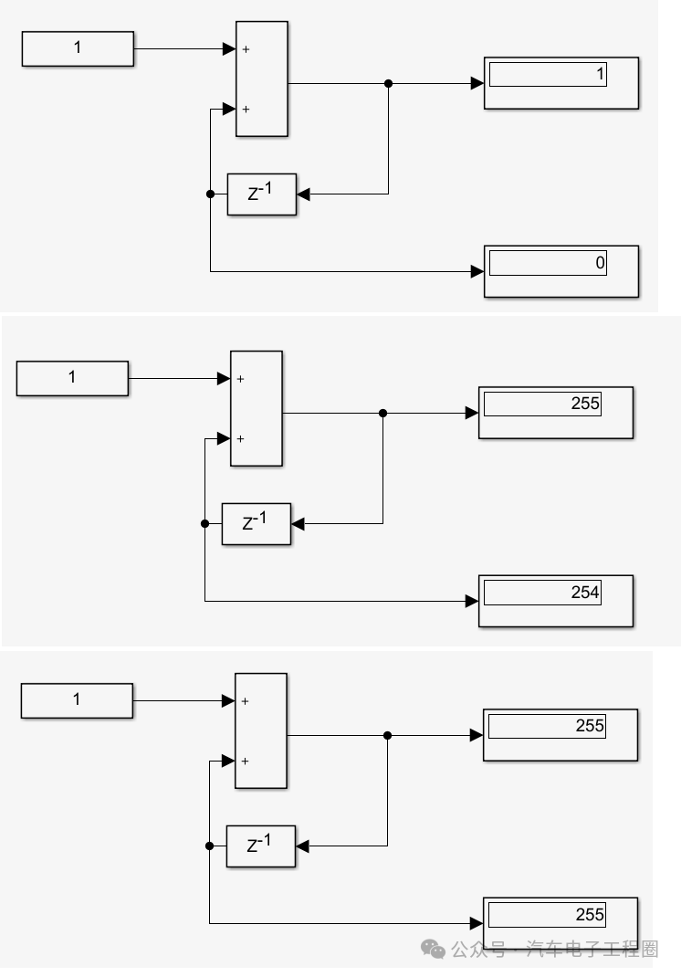
Regarding the aforementioned data overflow, some may argue that a result of 0 after overflow is what they desire. However, note that this demonstration is merely the result in the Simulink simulation environment, and the actual ECU results may differ, affecting other variable values in the ECU software, thus posing risks and hazards to vehicle operation.However, some may argue that an overflow resulting in 255 is not their intended design. So how should data overflow be handled in this case?If you expect the result to reset (to zero) after reaching the upper limit, you can adopt the following approach, which resets (to zero) upon overflow.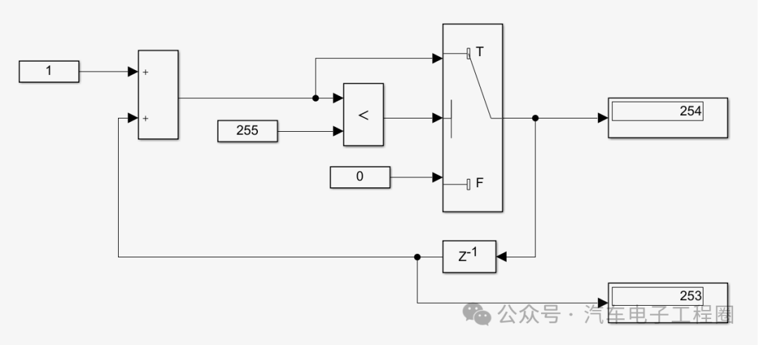
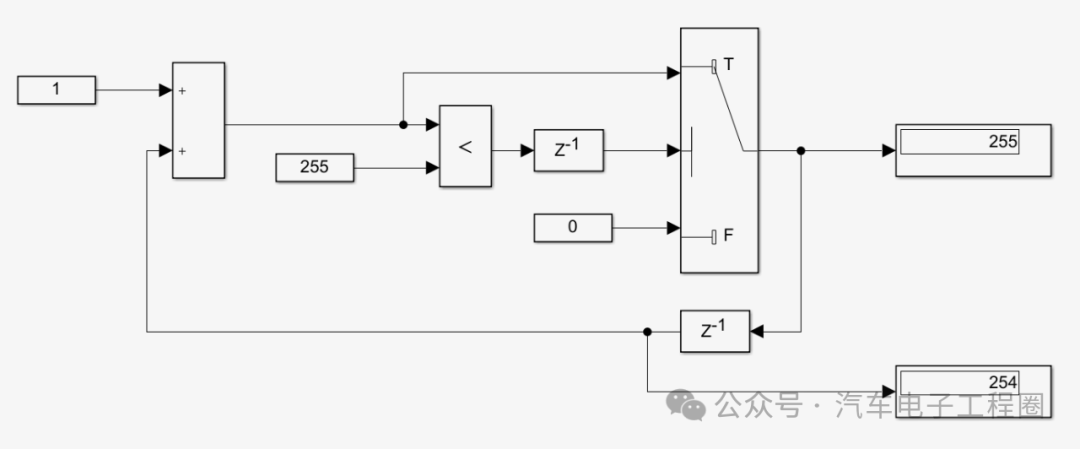
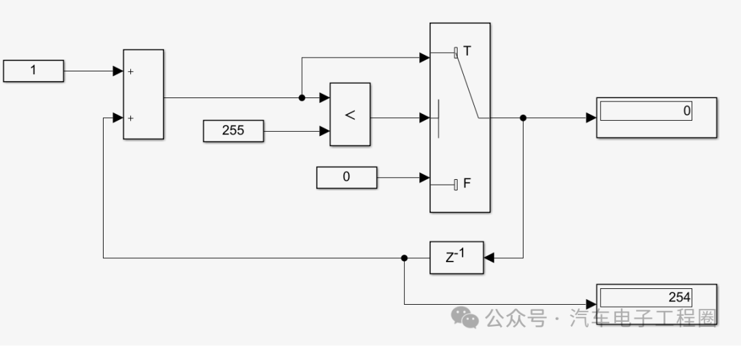 Here, the addition module still needs to be configured to prevent data overflow. This can indeed achieve a reset to zero upon overflow, but note that there is a problem with this method: the upper limit value is not reached, meaning the output variable of uint8 can only reach a maximum value of 254, not 255.To ensure that the output data range can reach 0-255, we can improve this by adding a Delay module, as shown below. Then, check the initial value requirements of the output variable. If the initial value is required to be 1, set the initial value of the delay module to 1, so that the initial algorithm remains consistent.
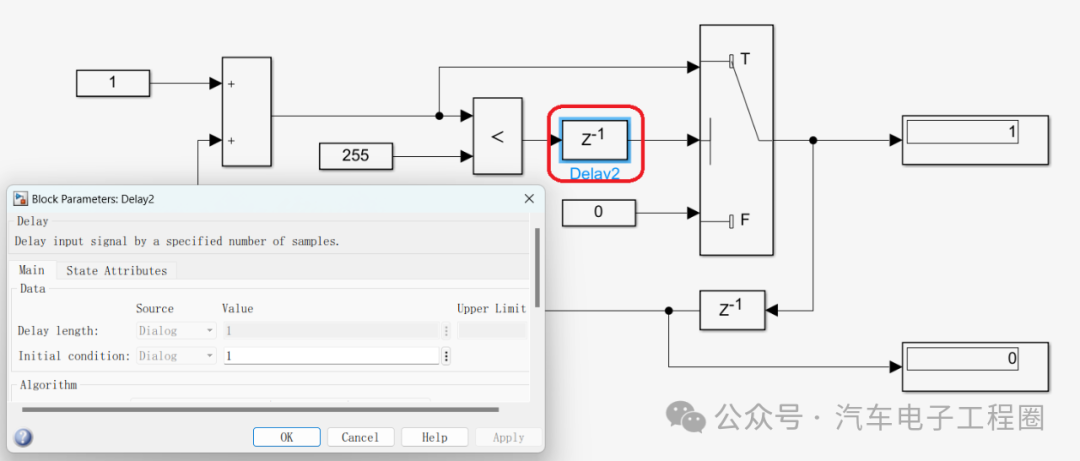 When the addition module first outputs (254+1), it will output 255, not reset to zero. Instead, it will wait for one cycle. When the addition module outputs (255+1) the second time, it will still output 255, and at this point, the output variable will reset to zero. Of course, this method still has room for optimization, but the focus here is to provide a general idea.
 3 ConclusionThe above is a simple discussion on data overflow using the addition module. It may seem like just a configuration option, but its importance is self-evident. Delving into ECU software model development and paying attention to these details is extremely important.Creating content is not easy, so please like, bookmark, and follow.!( Qian Yixing (formerly known as Automotive Electronics Engineering Circle) For those interested, please add the group owner: prOmiseyes, with a note: company + position to join the group. Limited to automotive industry personnel.
Articles in the ECU application layer software model series are continuously updated, teaching you application layer development from scratch:
- An example of building an ECU application layer software model 1 (qq.com)
- How to automatically generate code for ECU application layer software model 2 (qq.com)
- How to run ECU application layer software periodically 3 (qq.com)
- Code generation configuration related to ECU application layer software model and hardware 4 (qq.com)
- Data dictionary DD in ECU application layer software model 5 (qq.com)
- Data dictionary storage classes in ECU application layer software model 6 (qq.com)
- Fixed-point implementation in ECU application layer software model 7 (qq.com)
- Five fixed-point implementation methods in ECU application software model 8 (qq.com)
- Custom storage classes in ECU application layer software model 9 (qq.com)
- Summary of model generation code in ECU application layer software model 10 (qq.com)
- CAN reception in ECU application layer software model 11 (qq.com)
- Data stream reception of CAN messages in ECU application layer model 12
- How to leverage AI in ECU software development? Application of Kimi in MBD development environment 13
-
Detailed explanation of unit test coverage CC, DC, and MCDC in ECU application layer model 14
-
Application and principles of calibration quantities and observed quantities in ECU application layer model development 15
-
Usage of for loops in ECU application layer model development 16
- Usage of if-else in ECU application layer model development 17
- Initialization functions in ECU application layer model development 18
-
Counter in ECU application layer model development 19
-
Basics of the Assignment module in ECU application layer model development 20
-
Application of the Delay module in ECU application layer model development 21
-
If-else vs switch-case in ECU application layer model development 22
- Data dictionary of Simulink.Signal in ECU application layer model development 23