Click the blue text
Follow us
1. Overview
CAN stands for Controller Area Network, which is an ISO standardized serial communication protocol and one of the most widely used field buses internationally.
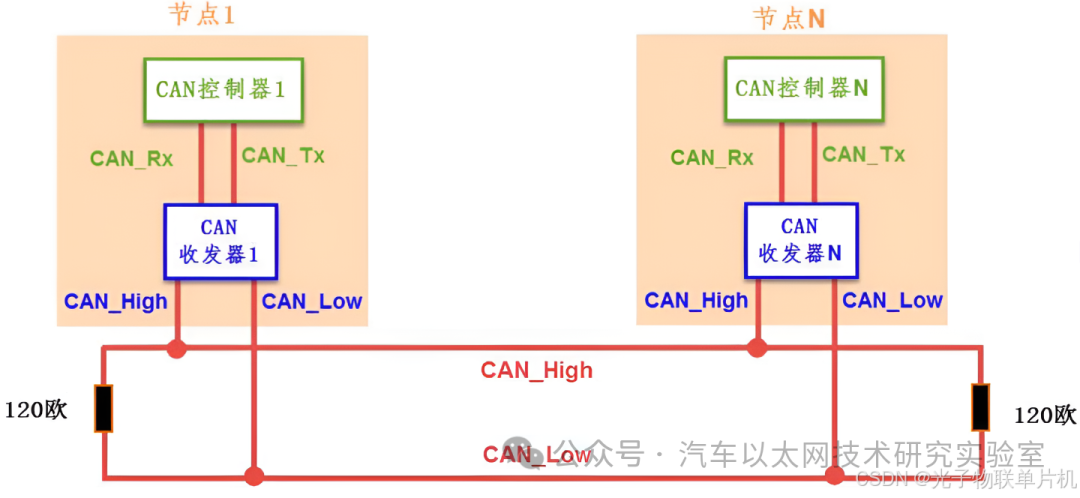
CAN communication uses only two signal lines, namely CAN_High and CAN_Low. The CAN controller determines the bus level based on the potential difference between these two lines. The bus level is divided into dominant and recessive states, one of which must be present. The sender transmits messages to the receiver by changing the bus level.
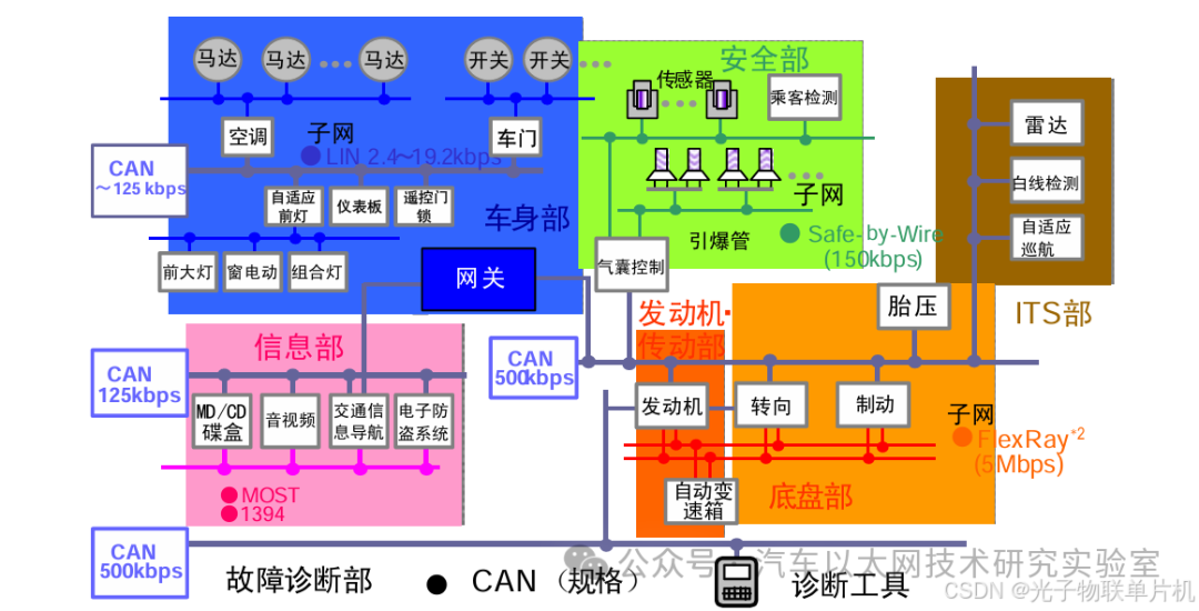
CAN bus is widely used in vehicles:
This article introduces the basic concepts of the CAN interface of the STM32 microcontroller, its internal structure, baud rate configuration, reception filter configuration, and examples of data communication using the CAN interface.
2. Basic Composition of CAN Network
A typical CAN network consists of multiple nodes, each containing at least one CAN controller and one CAN transceiver. Additionally, the network requires appropriate physical media, such as cables and connectors, to connect the various nodes.
The STM32F407VET6 microcontroller has a built-in CAN controller, and by connecting an external CAN transceiver (such as TJA1050/TJA1042), it can form a CAN node to communicate with other nodes.
3. CAN Structure and Features of STM32 Microcontroller
1. Basic Structure Diagram of STM32F4 Microcontroller CAN

The CAN core
is the core of the CAN controller, containing a series of control and status registers. By configuring these registers, key parameters such as the operating mode, baud rate, error detection, and recovery strategies of the CAN controller can be set. The core is also responsible for handling arbitration, error detection, frame transmission, and reception on the bus.
Transmission mailbox
is a buffer used to temporarily store messages to be sent. Each mailbox can hold a complete CAN message along with relevant control information. In certain STM32 series products, such as F1, F4, and F7, at least three transmission mailboxes are provided, allowing multiple messages to be prepared and sent concurrently, thus improving communication efficiency.
Reception FIFO
is used to temporarily store valid messages received from the CAN bus. When the CAN controller receives a message, it places it in the reception FIFO, from which the application can retrieve and process these messages. The FIFO design helps avoid data loss during reception, especially when multiple messages are received in quick succession.
Reception filter
is used to filter the messages received from the CAN bus. Only messages that match the filter will be stored in the reception FIFO, thus reducing unnecessary processor load and allowing the system to focus only on specific messages of interest. Filters can be configured based on various rules, such as identifiers and identifier masks.
2. Basic Features of STM32F4 Microcontroller CAN
The STM32F4 chip comes with a bxCAN controller (Basic Extended CAN), requiring only an external CAN transceiver, which is typically an 8-pin chip, such as the TJA1050, to interact with the CAN network. It supports both 2.0A and B versions of the CAN protocol.
● Supports 2.0 A and 2.0 B Active versions of the CAN protocol
● Bit rate up to 1 Mb/s
● Supports time-triggered communication schemes
Transmission
● Three transmission mailboxes
● Configurable transmission priority
● SOF transmission timestamp
Reception
● Two reception FIFOs with three levels of depth
● Adjustable filter groups:
— 28 filter groups shared between CAN1 and CAN2
● Identifier list functionality
● Configurable FIFO overflow
● SOF reception timestamp time-triggered communication scheme
● Disable automatic retransmission mode
● 16-bit free-running timer
● Management of timestamps in the last two data bytes sent
● Maskable interrupts
● Efficient mailbox mapping implemented in a unique address space via software
4. CAN Protocol Frame Format
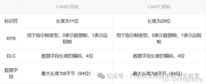
The data frame is the most commonly used frame, consisting of 7 segments. Depending on the length of the arbitration segment ID code, it is divided into standard frames (CAN2.0A) and extended frames (CAN2.0B), with different identifier (ID) lengths: the standard format is 11 bits, and the extended format is 29 bits.
Data frame format:

1. Start Field
SOF = Start of Frame
2. Arbitration Field
ID = Identifier
RTR = Remote Transmission Request bit, distinguishes between data frames and remote frames
3. Control Field
IDE = Extended Identifier flag, distinguishes between standard and extended formats
r0 = Reserved bit, leaving space for future protocol upgrades
DLC = Data Length
4. Data Field
Length of 0 to 8 bytes
5. CRC Field
CRC = Cyclic Redundancy Check code
6. ACK Field
ACK = Acknowledgment bit
7. End FieldEOF = End of Frame
Whether to use a standard or extended CAN frame depends on specific application requirements. If a smaller amount of data needs to be transmitted and the identifier length does not exceed 11 bits, the CAN standard frame can be chosen. For applications requiring larger data amounts and longer identifiers, the CAN extended frame should be selected. Generally, both parties in CAN communication will agree in advance on whether to use the standard or extended frame protocol.
5. CAN Communication Baud Rate of STM32F407VET6
Since CAN is an asynchronous communication protocol without a clock signal line, the various nodes connected to the same bus network communicate using a predetermined baud rate, similar to serial asynchronous communication.
Additionally, CAN uses a “bit synchronization” method to resist interference and absorb errors, ensuring correct sampling of bus level signals for normal communication.
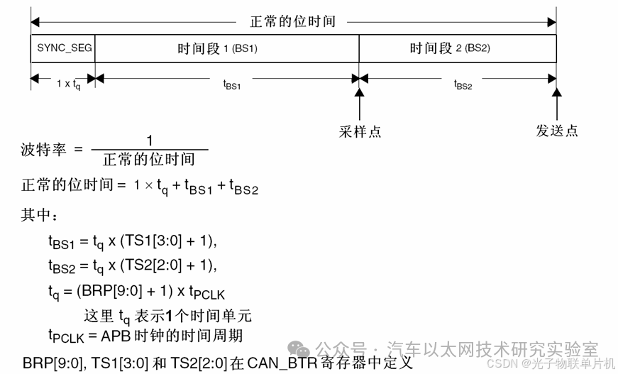
The nominal time for each bit is divided into three segments:
● Synchronization Segment (SYNC_SEG): The expected bit change occurs within this time segment. Its value is fixed at 1 time unit (1 x tCAN).
● Time Segment 1 (BS1): Defines the position of the sample point. It includes PROP_SEG and PHASE_SEG1 in the CAN standard.
Its value can be programmed from 1 to 16 time units but can also be automatically extended to compensate for phase drift caused by frequency differences among nodes in the network.
● Time Segment 2 (BS2): Defines the position of the transmission point. It represents PHASE_SEG2 in the CAN standard. Its value can be programmed from 1 to 8 time units but can also be automatically shortened to compensate for negative phase drift.

Taking the STM32F407VET6 as an example, the CAN clock is connected to APB1, and the APB1 clock is 42M.
BRP[9:0]: Baud Rate Prescaler, this register is configured to 23.
TS2[2:0]: Time Segment 2, this register is configured to 2.
TS1[3:0]: Time Segment 1, this register is configured to 2.
According to the baud rate formula:
tBS1 = tq * (TS1[3:0] + 1).
tBS2 = tq * (TS2[2:0] + 1).
tq = (BRP[9:0] + 1) x tPCLK.
tPCLK = 1/42000000.
Baud rate = 1/(tq + tBS1 + tBS2)
= 1/tq * (1 + (TS1[3:0] + 1) + (TS2[2:0] + 1))
= 42000000 / ((BRP[9:0] + 1) * (1 + (TS1[3:0] + 1) + (TS2[2:0] + 1)))
The baud rate calculation result is
42000000 / ((23 + 1) * (1 + (2 + 1) + (2 + 1))) = 250000 bps.
Generally, CAN baud rates are 250k, 500k, 1M, 125k. We can easily adjust the baud rate by changing the baud rate prescaler, as they are in a multiplicative relationship.
6. CAN Reception Filter Configuration of STM32F407VET6
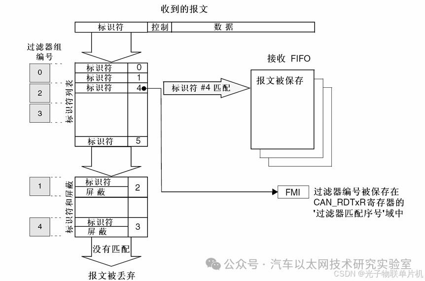
The configuration of the CAN filter is used to filter the messages received by CAN. In STM32 chips, CAN messages can be filtered to omit the processing by the MCU. In the CAN protocol, the message identifier does not represent the address of the node but is related to the priority of the message. The sender broadcasts the message to all receivers. When a node receives a message, it decides whether it needs the message based on the value of the identifier. If needed, it is copied to SRAM; if not, the message is discarded without software intervention.
To meet this requirement, CAN provides 28 configurable and adjustable filter groups (27-0), each consisting of two 32-bit registers, CAN_FxR1 and CAN_FxR2, to receive only the messages needed by the software. Hardware filtering saves MCU overhead; otherwise, software filtering would occupy some MCU resources.
The bit width of each filter group can be set individually to meet different application needs. Depending on the bit width, it can be configured as one 32-bit filter and two 16-bit filters.
● One 32-bit filter includes: STDID[10:0], EXTID[17:0], IDE, and RTR bits
● Two 16-bit filters include: STDID[10:0], IDE, RTR, and EXTID[17:15] bits
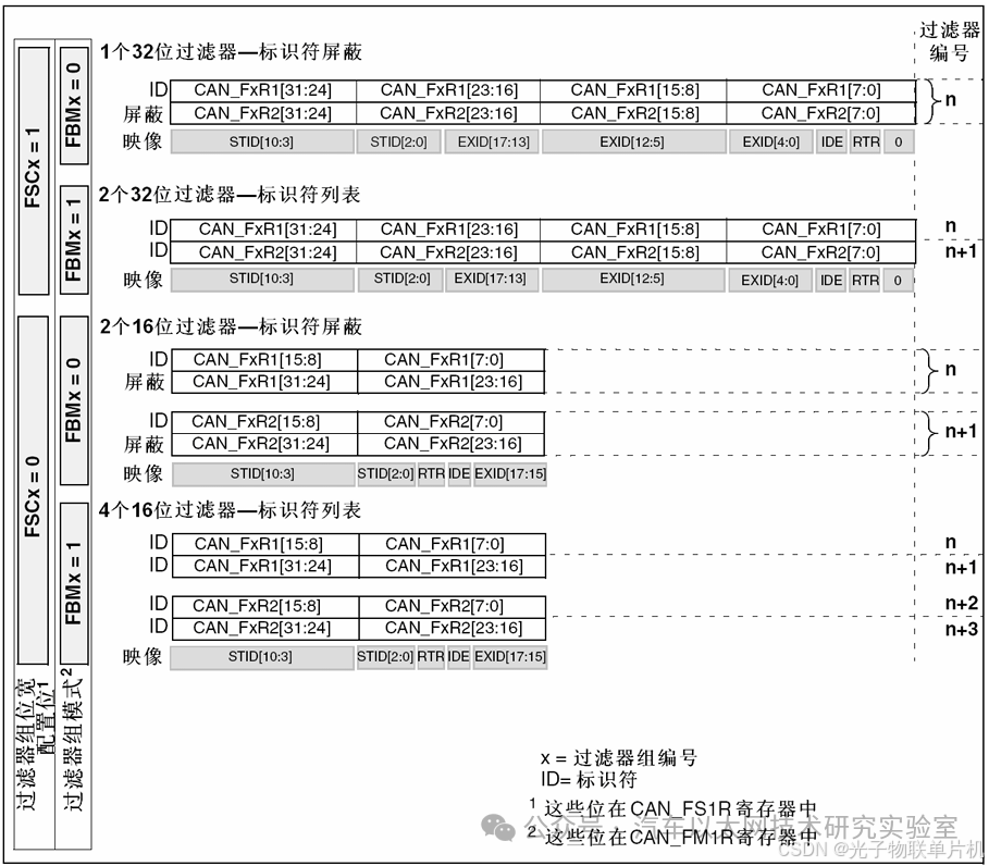
CAN filters can also be divided into masking mode and identifier list mode.
In the identifier masking mode: FxR1 is the identifier matching value, and FxR2 is the mask code. This means that a bit in FxR2 must match the corresponding position in the identifier of the received frame to pass through the filter. A bit in FxR2 that is 0 indicates that the corresponding bit in FxR1 does not need to match the received frame.
In the identifier list mode: FR1 and FR2 are the identifiers to be matched. The identifier of the received frame must match one of them to pass through the filter. All filters are in parallel; a message is considered valid if it can pass through any one filter.
For example:
Matching ID 0x200, mask 0x000, all ID numbers can pass
Matching ID 0x200, mask 0x700, IDs from 0x200 to 0x2FF can pass
Matching ID 0x200, mask 0x7FF, only 0x200 can pass
For beginners, setting the mask to 0 is sufficient to receive all frames on the CAN bus.
7. CubeMX Configuration for a CAN Data Transmission and Reception Example
Connect the TTL to CAN module to the development board, and power the board with a USB cable.
Use two Dupont wires to connect the module to the CAN box
Module CANH connected to CAN box CANH
Module CANL connected to CAN box CANL
The CAN box is connected to the computer via USB.

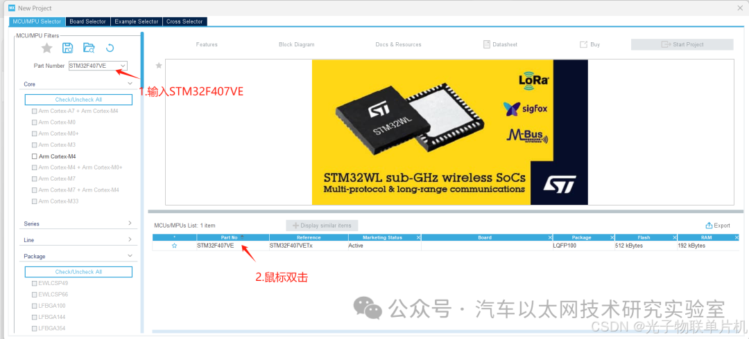
Open STM32CubeMX software and create a new project
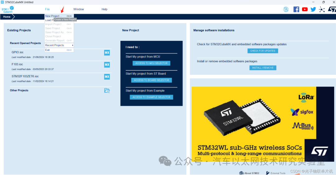
Enter STM32F407VE in the Part Number field, then double-click to create a new project
Configure the download port pins
Configure the external crystal oscillator pins

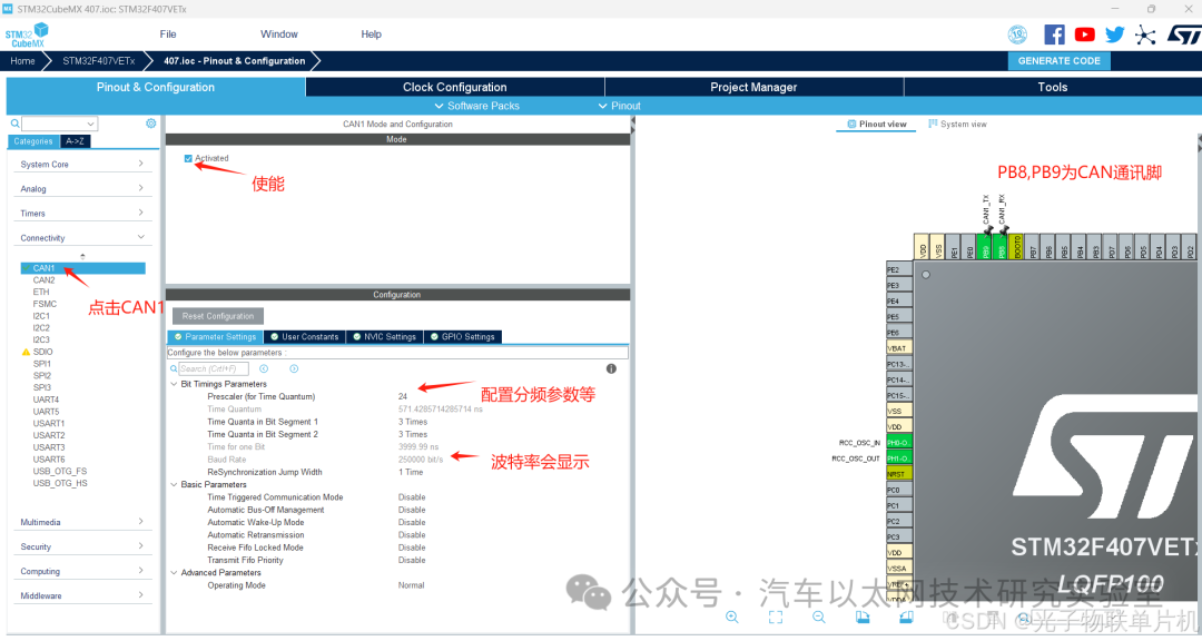
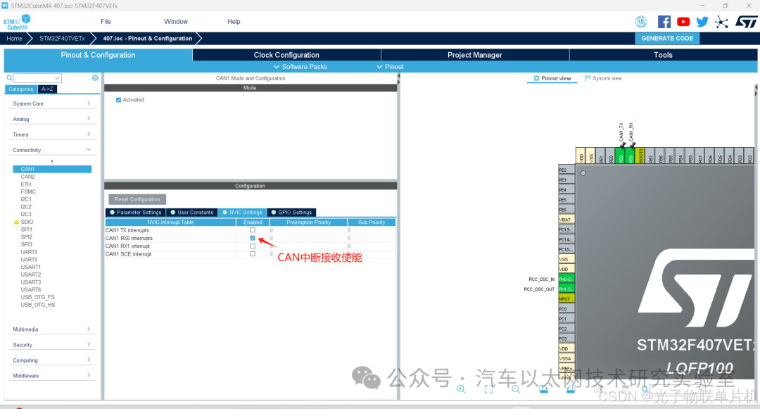
Configure CAN1, with a baud rate of 250K, PB8 and PB9 as the transmission and reception pins
Configure the system main frequency to 168MHz, using an external crystal oscillator

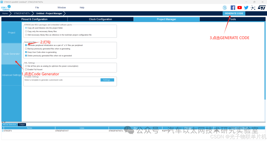
Configure the project file name, save path, and KEIL5 project output method

Generate the project
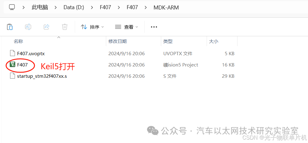
Open the project with Keil5
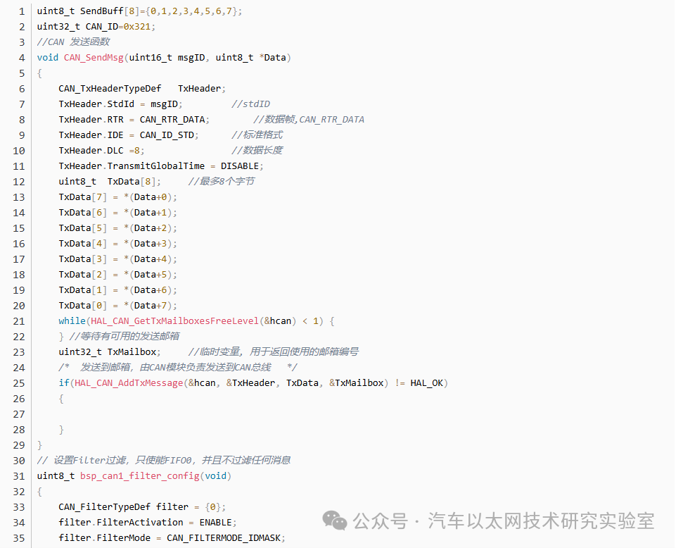
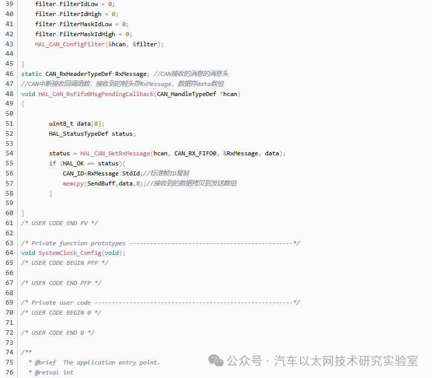
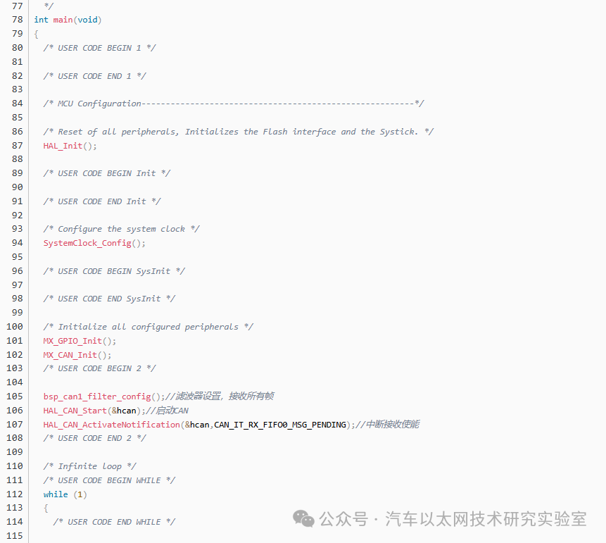
Add code
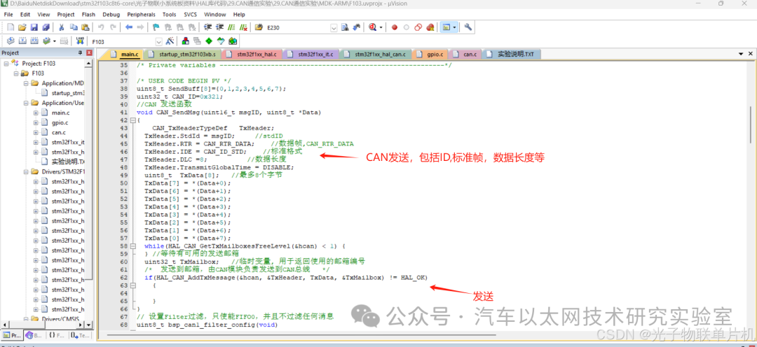
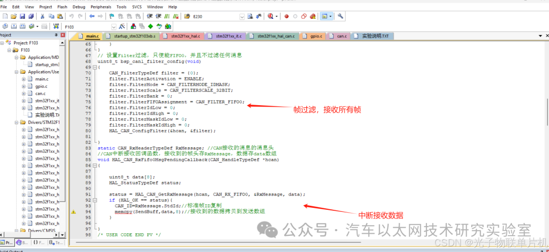
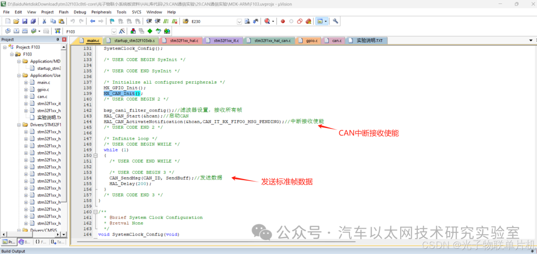
Main code

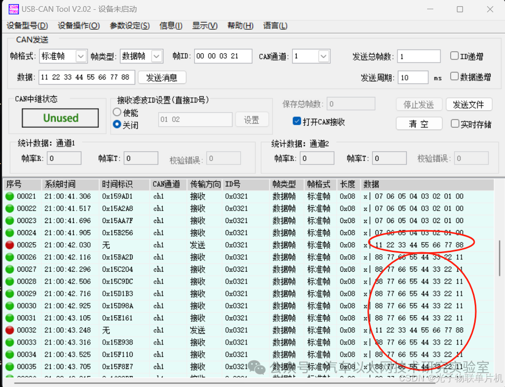
Experimental Results
Open the computer’s upper computer software, send a standard frame to the board with ID 0x321, content 0x11, 0x22, 0x33, 0x44, 0x55, 0x66, 0x77, 0x88. The board will change the content of the sent standard frame and send it back to the computer’s upper computer. The red data is sent from the computer, and the green data is sent from the board.
8. Conclusion
The CAN protocol is gradually being widely used in various fields such as industrial control, automotive, aerospace, shipping, medical devices, and smart homes due to its high performance, reliability, and flexibility.


*Disclaimer: This article is original or forwarded by the author. If it inadvertently infringes on someone’s intellectual property, please inform us for deletion.The above images and text are sourced from the internet. If there is any infringement, please contact us in a timely manner, and we will delete it within 24 hours.The content of the article represents the author’s personal views, and the Automotive Ethernet Technology Research Laboratory reprints it only to convey a different perspective, not representing the Automotive Ethernet Technology Research Laboratory’s agreement or support for this view. If there are any objections, please feel free to contact the Automotive Ethernet Technology Research Laboratory.
Original link:
https://blog.csdn.net/zy2232652/article/details/142453091