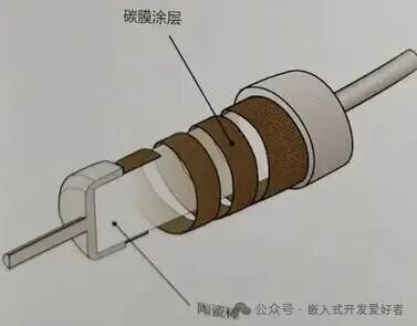
A resistor is a component that produces resistance. Its main function is to impede the flow of current in a conductor. The internal structure of a carbon film resistor is shown in the figure below.
1.1.1 Parameters of Resistors
When understanding resistors in a production environment, we need to focus on the following parameters:
1)Resistance Value
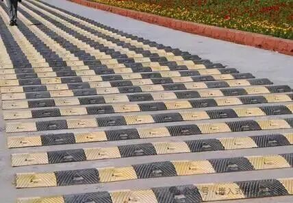
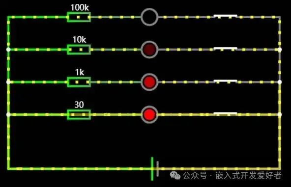
The greater the resistance value, the stronger the ability to impede current. Conversely, a smaller resistance value indicates a weaker ability to impede current. We need to select a resistor with an appropriate resistance value based on the actual circuit requirements.
2)Power
The rated power of a resistor refers to the maximum power that the resistor can dissipate or withstand while operating safely for an extended period under normal climatic conditions (such as atmospheric pressure, ambient temperature, etc.). For example, if the resistor power is 1/4W, and the resistance value is 1k, then according to the formula P=I2R=>0.25W= I2* 1000Ω=》I=0.015A =15mA, operating a current of 15mA through this resistor for a long time can easily damage it.
3)Accuracy
Generally, the accuracy of resistors is typically 1% and 5%, with precision resistors being 0.1% and so on. The higher the accuracy, the more expensive the resistor. A 0.1% resistor costs about ten times that of a 1% resistor, and a 1% resistor costs about 1.3 times that of a 5% resistor.
1.1.2 Fixed Resistors
Most resistors used in general circuits are fixed resistors, which are also the most common type in our daily lives. They can be roughly classified into the following categories based on manufacturing processes.
1)Carbon Film Resistors
(1)Purchase Link
https://item.szlcsc.com/3140120.html
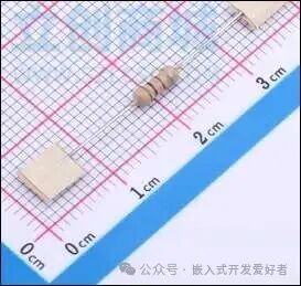
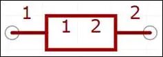
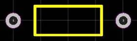
(2)Physical Image, Schematic, Package
(3)Data Sheet
(4)Application Scenarios
Carbon film resistors are mainly used in household appliances and other civilian fields.
2)Metal Film Resistors
(1)Purchase Link
https://item.szlcsc.com/754322.html
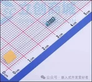
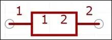
(2)Physical Image, Schematic, Package

(3)Data Sheet
(4)Application Scenarios
Metal film resistors have higher accuracy and are generally used in precision instruments or medical devices.
3)Wirewound Resistors
(1)Purchase Link
https://item.szlcsc.com/631181.html
https://item.szlcsc.com/3236618.html
(2)Physical Image, Schematic, Package
(3)Data Sheet
(4)Application Scenarios
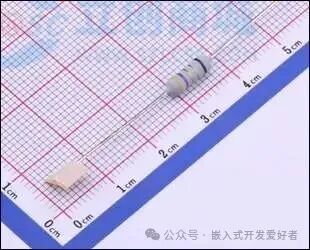
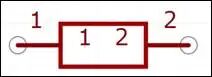
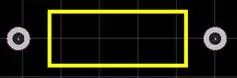
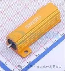
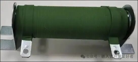
Wirewound resistors are made by tightly winding metal wire around a non-conductive ceramic, glass, or plastic core. These resistors are characterized by their ability to withstand high power (e.g., 5W, 10W, 20W), have a very low temperature coefficient, and provide high precision and stability, commonly used in high power, overload protection, or harsh environmental conditions. Due to the high inductance of these resistors, they have poor high-frequency response and cannot be used in high-frequency applications.
4)Thick Film Resistors
(1)Purchase Link
https://item.szlcsc.com/650544.html
(2)Physical Image, Schematic, Package
(3)Data Sheet
(4)Application Scenarios
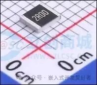
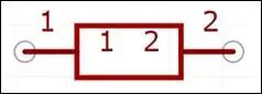
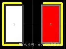
Thick film resistors are cost-effective, have low accuracy, and are widely used in mainstream electronic products;
5)Thin Film Resistors
(1)Purchase Link
https://item.szlcsc.com/112001.html
(2)Physical Image, Schematic, Package
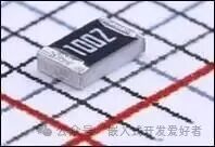
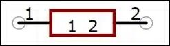
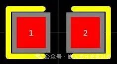
(3)Data Sheet
(4)Application Scenarios
Thin film resistors are more expensive and have higher accuracy, used more in precision instruments, military, and aerospace applications where high precision is required.
1.1.3 Variable Resistors
The manufacturing process of variable resistors is similar to that of fixed resistors, mainly consisting of thin film resistors, metal film resistors, and wirewound resistors. Compared to fixed resistors, they have an additional adjustment pointer for resistance. Common package types include rotary potentiometers, sliding potentiometers, trimmer potentiometers, multi-turn potentiometers, etc., as shown in the figure below:
(1)Purchase Link
https://item.szlcsc.com/120223.html
(2)Physical Image, Schematic, Package
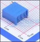
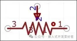
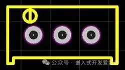
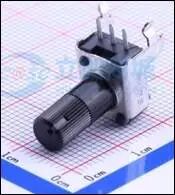
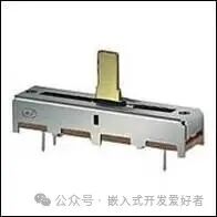
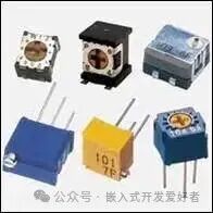
(3)Data Sheet
(4)Application Scenarios
Variable resistors are generally used in homes, businesses, stage lighting, etc., to adjust the brightness and color of lights by controlling the resistance value.
1.1.4 Special Resistors
1)Photoresistors
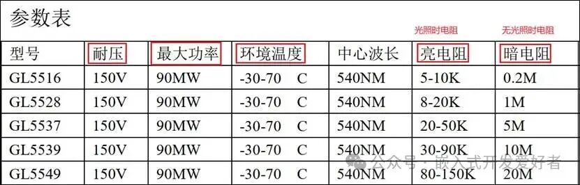
The working principle of a photoresistor: the resistance decreases as the light intensity increases. It is generally used in light detection, lighting control, alarm systems, etc.
(1)Purchase Link
https://item.szlcsc.com/10620.html
(2)Physical Image, Schematic, Package
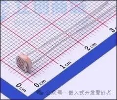
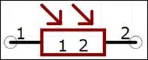
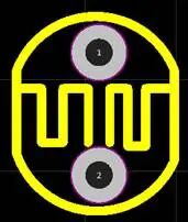
2)Varistors
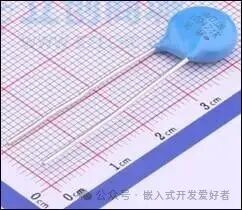
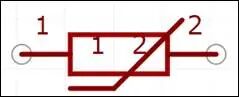
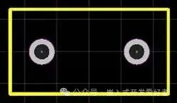
The working principle of a varistor: when the voltage across the varistor exceeds the rated voltage, the resistance decreases. It is generally used for absorbing overvoltage, surge protection, and lightning protection.
(1)Purchase Link
https://item.szlcsc.com/9271.html
(2)Physical Image, Schematic, Package
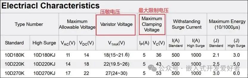
10D180K=》10 indicates diameter in millimeters, D indicates round shape, S indicates square shape.
180=》the first two digits are significant figures18, and the last digit indicates the number of zeros, so the varistor voltage is 18V.
K=》indicates tolerance ±10%.
Maximum Allowable Voltage:Maximum allowable voltage (maximum operating voltage).
Varistor Voltage:Varistor voltage.
Maximum Clamping Voltage:Maximum clamping voltage.
1.1.5 Identifying Resistor Values
1)Direct Marking Method
The direct marking method involves directly labeling the resistor’s type, nominal resistance value, allowable deviation, and rated power on the surface of the resistor.
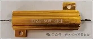

Figure1 Figure2
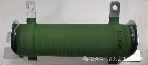
Figure3
Figure1 indicates nominal resistance value4Ω, toleranceJ=±5%, RX indicates wirewound resistor, 24 is the model number.
Figure2 indicates nominal resistance value200Ω, toleranceJ=±5%.
Figure3 indicates nominal resistance value100Ω, toleranceJ=±5%.
Generally, the accuracy codes areA=±0.05%, B=±0.1%, C=±0.25%, D=±0.5%, F=±1%, G=±2%, J=±5%, K=±10%, M=±20%.
The unit symbols for nominal resistance values in the direct marking method are shown in the table below.
|
Character Symbol |
Unit and Order of Magnitude |
Character Symbol |
Unit and Order of Magnitude |
|
R |
Ω(100) |
M |
MΩ(106Ω) |
|
k |
kΩ(103Ω) |
2)Two Significant Figures Resistor Reading Method
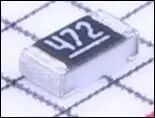
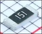
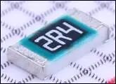
Two Significant Figures Resistor Reading Method indicates the resistance value using three digits on the resistor body, generally used for ±5% accuracy resistors. Its first2 significant figures, the3rd digit indicates the number of zeros added after the significant figures“0”, this digit will not have letters. Among them,R indicates the decimal point.
For example:“472” indicates“4700Ω”, “151” indicates“150Ω”.If it is a decimal. it is represented by“R” indicating“decimal point”. and occupies one significant figure, the other two digits are significant figures. For example:“2R4” indicates“2.4Ω”, “R15” indicates“0.15Ω”。
3)Three Significant Figures Resistor Reading Method
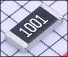
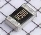
Three Significant Figures Resistor Reading Method indicates the resistance value using four digits on the resistor body, generally used for ±1% accuracy resistors. Its first3 digits are significant figures, the4th digit indicates the number of zeros added after the significant figures“0”, this digit will not have letters. Among them,R indicates the decimal point.
For example:“1001” indicates1000Ω.“R500” indicates,0.5Ω(500mΩ)。
4)Precision Resistor Reading Method
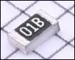
The precision resistor reading method is represented by two digits plus one letter, generally used for ±0.1% accuracy resistors, for example:01B etc.
Precision resistor value reference table:
|
Code |
Value |
Code |
Value |
Code |
Value |
Code |
Value |
|
01 |
100 |
25 |
178 |
49 |
316 |
73 |
562 |
|
02 |
102 |
26 |
182 |
50 |
324 |
74 |
576 |
|
03 |
105 |
27 |
187 |
51 |
332 |
75 |
590 |
|
04 |
107 |
28 |
191 |
52 |
340 |
76 |
604 |
|
05 |
110 |
29 |
196 |
53 |
348 |
77 |
619 |
|
06 |
113 |
30 |
200 |
54 |
357 |
78 |
634 |
|
07 |
115 |
31 |
205 |
55 |
365 |
79 |
649 |
|
08 |
118 |
32 |
210 |
56 |
374 |
80 |
665 |
|
09 |
121 |
33 |
215 |
57 |
383 |
81 |
681 |
|
10 |
124 |
34 |
221 |
58 |
392 |
82 |
698 |
|
11 |
127 |
35 |
226 |
59 |
402 |
83 |
715 |
|
12 |
130 |
36 |
232 |
60 |
412 |
84 |
732 |
|
13 |
133 |
37 |
237 |
61 |
422 |
85 |
750 |
|
14 |
137 |
38 |
243 |
62 |
432 |
86 |
768 |
|
15 |
140 |
39 |
249 |
63 |
442 |
87 |
787 |
|
16 |
143 |
40 |
255 |
64 |
453 |
88 |
806 |
|
17 |
147 |
41 |
261 |
65 |
464 |
89 |
825 |
|
18 |
150 |
42 |
267 |
66 |
475 |
90 |
845 |
|
19 |
154 |
43 |
274 |
67 |
487 |
91 |
866 |
|
20 |
158 |
44 |
280 |
68 |
499 |
92 |
887 |
|
21 |
162 |
45 |
287 |
69 |
511 |
93 |
909 |
|
22 |
165 |
46 |
294 |
70 |
523 |
94 |
931 |
|
23 |
169 |
47 |
301 |
71 |
536 |
95 |
953 |
|
24 |
174 |
48 |
309 |
72 |
549 |
96 |
976 |
|
Y=10-2 |
X=10-1 |
A=100 |
B=101 |
||||
|
C=102 |
D=103 |
E=104 |
F=105 |
For example, 01B indicates100*10=1000Ω.
5)Color Code Method
The principle of the resistor color code method is to indicate the resistance value and accuracy by painting different colored bands on the surface of the resistor. Generally, there are 4 or 5 color bands on a resistor, each representing a digit or a specific coefficient. The resistance value and accuracy can be determined based on the position and color of the color bands.
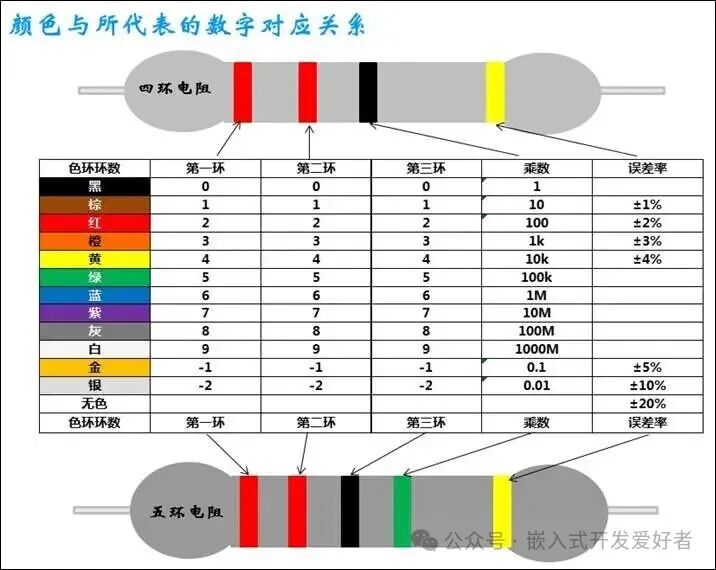
For a four-band resistor, the resistance value is:22*1±4%Ω.
For a five-band resistor, the resistance value is:220*100k±4%.
Note: The resistance value can be directly measured with a multimeter. It is generally rare to read the color bands.