In semiconductor manufacturing, the design of pressure differential gradients in electronic cleanrooms serves as a “physical firewall” to block the spread of contamination. By scientifically planning airflow direction and pressure differences, it ensures that air flows unidirectionally from higher cleanliness areas to lower cleanliness areas, achieving “zero contamination infiltration.” Here are five core strategies:
1.Gradient Decrease Principle: Establishing a Unidirectional Airflow Barrier
1.Cleanliness Level Gradient: Divide clean areas based on process requirements (e.g., ISO Class 3 core area, ISO Class 5 buffer area, ISO Class 7 logistics area), maintaining a pressure difference of 5-15Pa between adjacent areas (for example, the core area is 10Pa higher than the buffer area, and the buffer area is 5Pa higher than the ordinary area).
2.Typical Case: A 12-inch wafer factory achieved a particle concentration in the core area of below 0.1μm/m³ through pressure differential gradient design, improving product pass rate by 12%.
3.Key Point: The pressure differential value must be determined through airflow balance calculations to avoid excessive values that could make airtight doors difficult to open or lead to increased energy consumption.
2.Dynamic Monitoring and Intelligent Control: Responding to Process Fluctuations
1.Real-time Monitoring System: Install high-precision pressure differential sensors (with an accuracy of 0.1Pa) in key areas (such as air showers and transfer windows), with data transmitted to intelligent controllers.
2.Automatic Adjustment Mechanism: Dynamically adjust airflow using variable frequency fans or Venturi valves to maintain stable pressure differentials. For example, a chip factory uses AI algorithms to predict pressure differential changes and adjusts airflow in advance, keeping fluctuations within ±2Pa.
3.Alarm Thresholds: Set abnormal pressure differential thresholds (e.g., ±5Pa) to trigger audible and visual alarms or automatic shutdowns to prevent contamination spread.
3.Airtightness Enhancement: Eliminating “Air Leakage” Risks
1.Enclosure Structure: Use double-layer color steel plates filled with rock wool, applying sealing strips at joints to ensure an air leakage rate of <1%.
2.Door and Window Design: Select airtight rapid roll-up doors or interlocked transfer windows, installing inflatable sealing strips at door seams.
3.Process Penetrations: Foam seal equipment wall penetrations and pipeline gaps to avoid “short-circuiting” airflow.
4.Testing and Verification: Use pressure differential decay methods or infrared thermal imaging to test airtightness, ensuring compliance with ISO 14644-3 standards.
4.Airflow Organization Optimization: Eliminating “Dead Zones” and Turbulence
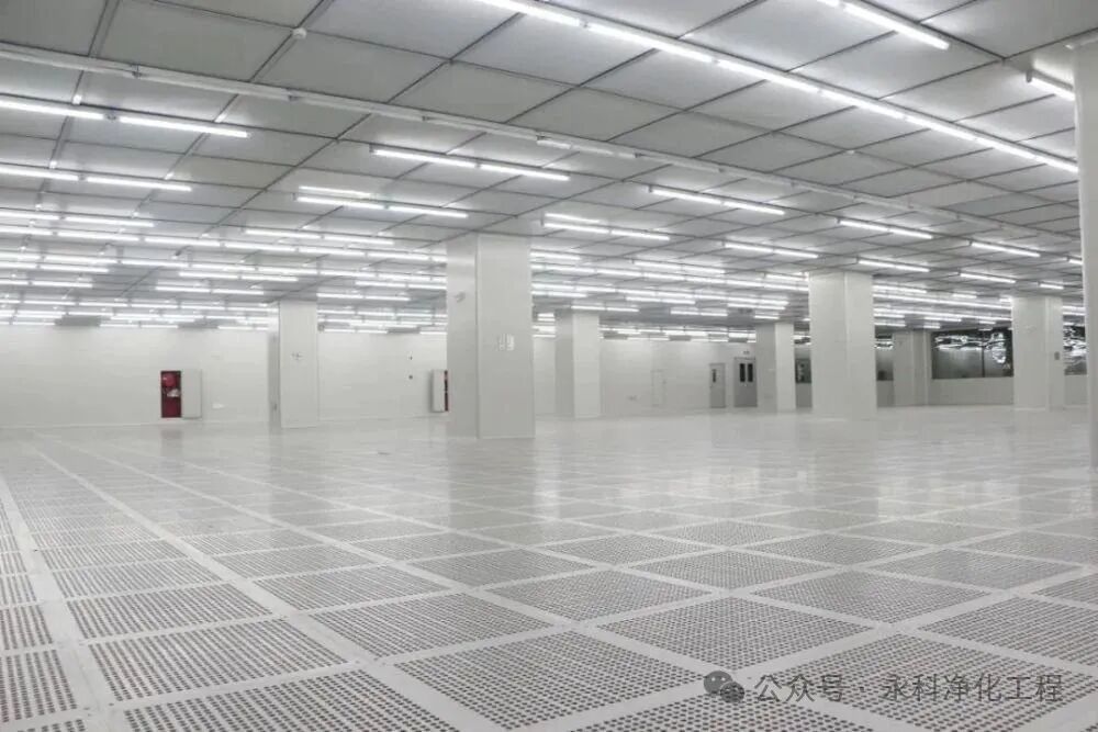
1.Air Supply Method: High cleanliness areas should use vertical unidirectional flow (FFU + raised floor) to ensure rapid particle removal; low cleanliness areas may use non-unidirectional flow (top supply and side return).
2.CFD Simulation: Use computational fluid dynamics (CFD) to simulate airflow distribution, optimizing supply and return vent locations to eliminate turbulence zones. For example, a COB packaging workshop improved particle settling speed in the core area by 30% after CFD optimization.
3.Equipment Layout: High-power equipment (e.g., photolithography machines) should be placed in the core airflow area, maintaining a distance of >1.5m from chemical delivery pipelines to avoid local turbulence.
5.Personnel and Logistics Management: Reducing “Human Contamination”
1.Personnel Purification: Establish a three-level purification process of changing rooms – airlock – air shower, requiring personnel to complete three changes and a 30-second air shower before entering the core area.
2.Logistics Channels: Use interlocked transfer windows or automated guided vehicles (AGVs) to avoid disrupting pressure differential balance during material handling.
3.Pressure Differential Visualization: Install pressure differential display screens or indicator lights in the workshop to provide real-time pressure differential status, training employees to operate according to standards.
4.Typical Case: A certain LED module factory reduced defect rates caused by human contamination from 0.8% to 0.2% through strict personnel and logistics management.
Industry Trends: Integration of Intelligence and Sustainability
1.Digital Twin Technology: Construct a virtual model of the cleanroom to optimize pressure differential control strategies through real-time data mapping, reducing physical debugging costs.
2.Low-carbon Operation: Use variable frequency fans, heat recovery devices, and AI energy optimization algorithms to reduce energy consumption of pressure differential control systems. For example, a company achieved a 25% reduction in fan energy consumption through intelligent control.
3.Adaptive Pressure Differential Adjustment: Combine machine vision technology to dynamically identify personnel positions and equipment status, achieving real-time adjustments of pressure differential gradients, further enhancing contamination prevention accuracy.
Fujian YongkeConclusion
The design of pressure differential gradients in semiconductor electronic cleanrooms essentially constructs a “micro-scale environmental immune system.” Through the comprehensive application of five strategies: gradient planning, dynamic control, airtightness enhancement, airflow optimization, and personnel management, it can achieve an upgrade from “passive purification” to “active defense.” For purification engineering companies, customized designs must be combined with customer process characteristics (such as quantum effect challenges in processes below 2nm) to help the semiconductor industry break through the dual bottlenecks of quality and efficiency.