
By丨Mobius ChenEngineer at Tencent Interactive Entertainment
The term “myth” refers to phenomena that are passed down through word of mouth but are difficult to prove or disprove.
Due to the black box nature of GPU hardware and driver implementations, we can only understand and speculate on their principles through the APIs provided by manufacturers and the abstract architectures. As a result, various performance myths circulate regarding interactions with GPUs. For example, “the bottleneck on mobile devices is bandwidth,” “overdraw is not a major concern on mobile devices,” and “vegetation requires a pre-pass,” among others. These optimization techniques sometimes leave us with only a partial understanding of the underlying principles, and at times, they become less applicable as hardware evolves, gradually turning into a form of mysticism.
The author hopes to qualitatively analyze these “myths” by combining existing materials to avoid inadvertently leading to negative optimizations. When conditions allow, I even hope to conduct some quantitative analysis experiments.
Mobile Architecture

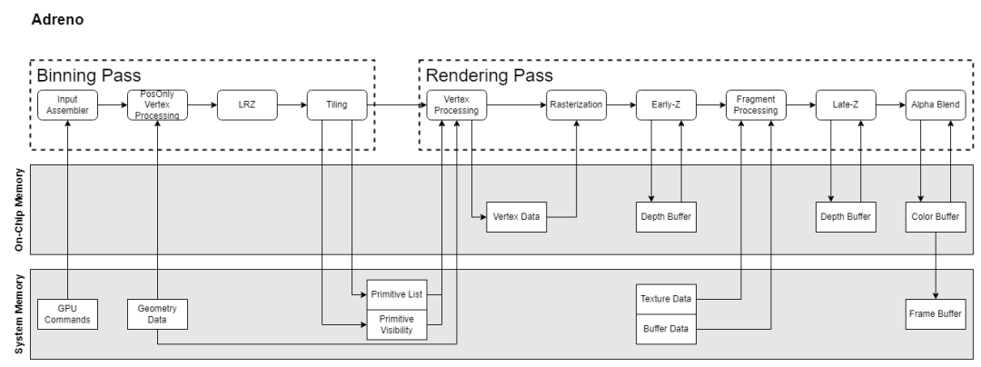

Let’s briefly review the GPU architectures of several manufacturers. Apple’s GPU architecture has no available documentation, so we can only tentatively refer to the PowerVR architecture documentation from years ago. Current mobile GPUs are all based on TBDR architecture, which consists of two passes: the Binning Pass and the Rendering Pass. The Binning Pass allocates various primitives to different tiles, and the Rendering Pass renders these tiles.
There is a wealth of information on GPU structures, so I will not elaborate further here. We will focus on a few functional points that differ across architectures and are related to the subsequent “myths.”
Hidden Surface Removal
The term “Hidden Surface Removal” comes from PowerVR’s HSR (Hidden Surface Removal) and typically refers to the GPU’s ability to eliminate primitives/fragments that are ultimately occluded, thereby avoiding the execution of their pixel shaders (PS) to reduce overdraw.
Adreno, Mali, and PowerVR handle hidden surface removal differently.
PowerVR’s HSR principle involves generating a visibility buffer that records the depth of each pixel for pixel-level fragment elimination. Since this is a per-pixel elimination, it must occur after rasterization, meaning each triangle must undergo rasterization. The visibility buffer determines which fragment’s PS to execute for each pixel. Therefore, PowerVR refers to its TBR (Tile Based Rendering) as TBDR (Tile Based Deferred Rendering). It is also noted that if a fragment’s depth cannot be determined during the vertex shader (VS) stage, it will wait until the fragment’s PS execution is complete to determine the depth before filling in the corresponding visibility buffer. This means that this fragment will block the generation of the visibility buffer. This architecture is based on PowerVR documentation from around 2015, and while Apple has inherited this architecture, it is unclear whether further architectural optimizations have been made since then.
Adreno implements hidden surface removal through a process called LRZ (Low Resolution Depth), which operates at the primitive level rather than the fragment level. During the Binning Pass, a Position-Only VS generates an LRZ buffer (a low-resolution z buffer) that compares the minimum depth of triangles with the z buffer to determine triangle visibility. After the Binning Pass, the visible triangle list is stored in SYSMEM, and during the render pass, rendering is based on this triangle list. Compared to PowerVR’s HSR, LRZ reduces rasterization overhead since it is performed during the binning pass. Additionally, there is an early-z stage in the render pass for fragment-level elimination. For fragments whose depth can only be determined during the PS stage, LRZ will skip them but will not block the pipeline.
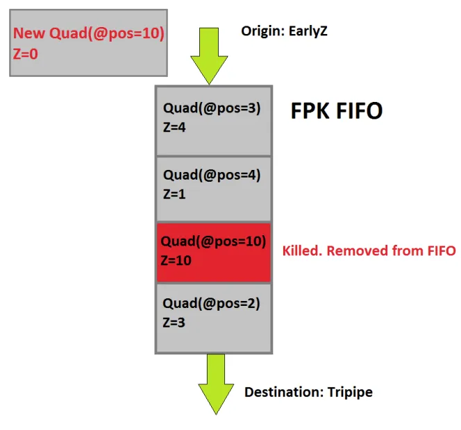
Mali’s hidden surface removal technique is called FPK (Forward Pixel Killing). Its principle is that all quads that pass Early-Z are placed in a FIFO queue, recording their positions and depths while waiting for execution. If a new Quad A enters the queue with the same position as an existing Quad B but with a smaller depth, Quad B will be killed and not executed. Early-Z can only eliminate the current quad based on historical data, while FPK can use the current quad to eliminate older quads to some extent. FPK is similar to HSR, but the difference is that HSR is blocking; it only executes the PS after the visibility buffer is fully generated. In contrast, FPK does not block and only kills PS that have not yet executed or are halfway through execution.
Execution of Vertex Shader
In PowerVR, the VS executes during the Binning Pass and is only executed once.
Both Adreno and Mali execute the VS twice. The first execution is “PosOnly Vertex Processing,” which only executes the position-related instructions in the VS to calculate position information for the Binning Pass.
The second execution of the VS in Mali occurs during the binning phase and is called “Varying Shading,” where only the non-position logic is executed. In contrast, Adreno’s second execution of the VS occurs during the rendering phase and executes the full VS.
Why is there this distinction? The next section, “VS Output,” will explain.
VS Output
The data produced during the VS stage is referred to as VS Output or Post-VS Attributes. The handling of this data varies across architectures.
In PowerVR, the full VS is executed during the Binning Pass, and the VS Output is written to system memory. During the Rendering Pass, it is read back.
In the Adreno architecture, after the Binning Pass, only two types of data are produced and written to system memory: Primitive List and Primitive Visibility. During the Rendering Pass, the VS is executed again to produce the VS Output. This data is not written back to system memory but is stored in On-Chip Memory (Local Buffer), allowing the PS stage to read directly from the Local Buffer.
This approach saves a significant amount of bandwidth consumption.
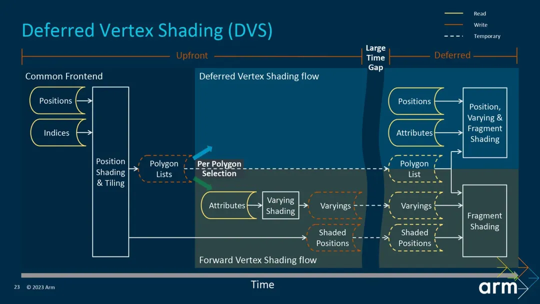
Before the fifth-generation GPU architecture Immortalis, Mali executed the second VS after the Binning Pass and wrote the VS Output to system memory, which was then read back during the rendering pass. This resulted in bandwidth consumption. The fifth-generation architecture introduced Deferred Vertex Shading (DVS), which delays Varying Shading until the rendering stage, allowing data to be stored directly in On-Chip Memory for subsequent PS use, achieving bandwidth savings.
It is claimed that this can save 20% – 40% of bandwidth.
Mobile Bandwidth as a Bottleneck
Bandwidth refers to the amount of data transmitted per unit of time, quantified as “bit width (bit wide) * frequency.” Given a fixed bit width, bandwidth can only be increased by raising the operating frequency. Higher frequencies require higher voltages, leading to increased power consumption. The relationship between power (P) and voltage (V) indicates that power consumption is proportional to the square of the voltage.
The statement “bandwidth is a bottleneck on mobile devices” arises from two aspects:
1. The development of bandwidth does not match the development of computing power.
2. Increases in bandwidth lead to higher power consumption.
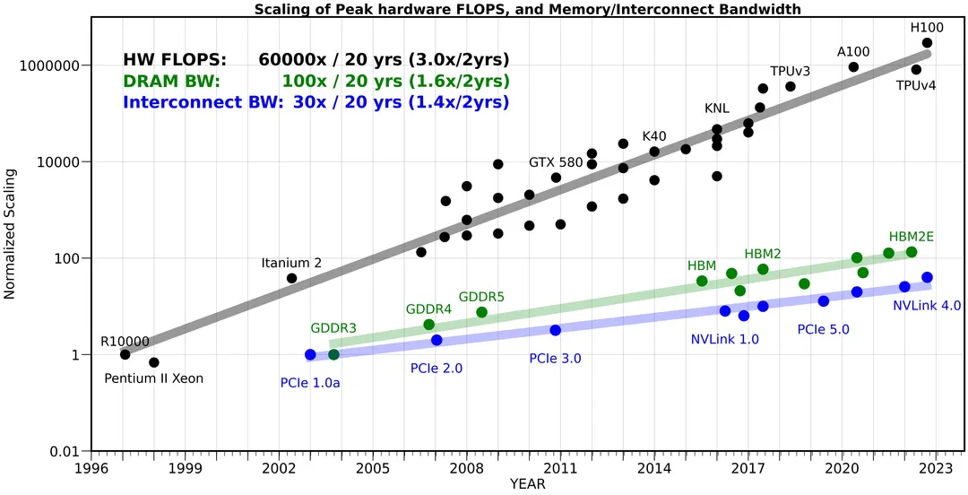
The following chart compares the development of computing power, memory bandwidth, and internal bandwidth, showing that over 20 years, hardware computing power has increased by 60,000 times, memory bandwidth by 100 times, while internal bandwidth has only increased by 30 times. The width of the road has increased several times, but the traffic volume has increased tens of thousands of times, making the road width a bottleneck.
This issue becomes even more severe on mobile devices. Due to limited chip area, the bit width cannot be made very large. On mobile devices, memory bit widths are generally 64-bit or 128-bit, while desktop devices can be 1024-bit wide, and graphics cards with HBM (High Bandwidth Memory) can reach 4096-bit wide. Higher bit widths imply greater area and cost. Therefore, mobile devices can only increase bandwidth by raising voltage. According to the previous formula, power (P) is proportional to the square of voltage (V). An increase in voltage exponentially raises the power consumption of mobile devices. Hence, we often say that “the major contributor to mobile power consumption is bandwidth.”
Avoid Branching in Shaders
This is a classic myth: “Do not use branches in shaders, as doing so means the shader must execute once for each side of the branch.”
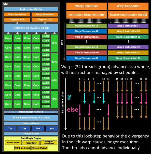
This statement is based on the principle of parallel execution in GPU SPs. SPs execute using a lockstep method, where all fibers (or threads) in the same wave (or warp) execute the same instruction simultaneously. Each fiber progresses simultaneously. SPs have a Mask function that can mask certain fibers during execution. This function is used to handle branches. When a branch is encountered, the fibers that should take the false path are masked out, and the true branch is executed; then the fibers that should take the true path are masked out, and the false branch is executed. This is what leads to the notion that shaders must execute once for each side of the branch.
This function is called “Divergency” and is not only used for handling logical branches but also for many other functions, such as quad overdraw.
However, branching conditions can be categorized into several types:
1. Constant conditions: These will be optimized out at compile time and will not produce branches.
2. Uniform conditions: If all fibers in the same wave follow the same branch condition, there should also be no branching.
3. Runtime variable conditions: This type has the most significant impact on performance.
The second point is often overlooked.
Additionally, different GPU architectures have varying sensitivities to divergency performance. From a theoretical standpoint, we can infer that the more fibers in a wave, the greater the cost of divergency. In Adreno, where each wave has a larger number of fibers, the impact of divergency is more pronounced.
In the Snapdragon Profiler, divergency can be observed through these two metrics: % Shader ALU Capacity Utilized and % Time ALUs Working.
Here are the meanings of these two metrics:
% Shader ALU Capacity Utilized: An important metric. When divergency exists, this metric will be less than “% Time ALUs Working.” For example, if “% Time ALUs Working” is 50% and “% Shader ALU Capacity Utilized” is 25%, it means half of the fibers are not working (masked due to divergence or triangle coverage). % Time ALUs Working: This indicates the proportion of cycles in which the ALU engine is working during busy cycles. Even if only one fiber is active in a wave, this metric counts as one. This differs from Fragment ALU Instructions Full/Half.
In other words, the divergency ratio = % Time ALUs Working – % Shader ALU Capacity Utilized
Mobile Devices Do Not Need to Worry Too Much About Overdraw
“Overdraw” literally means “drawing too much,” performing unnecessary work. Typically, overdraw refers to multiple overlapping triangles, where distant pixels are drawn first and then closer pixels, resulting in the distant pixels being discarded, thus wasting the PS of those distant pixels.
In the current TBDR architecture, after the binning stage, depth information is available through the VS, allowing for the elimination of distant triangles (or pixels) based on this depth information, thereby reducing subsequent PS overdraw. This mechanism is referred to as LRZ (Low Resolution Depth) in Adreno GPUs, HSR (Hidden Surface Removal) in PowerVR GPUs, and FPK (Forward Pixel Killing) in Mali. Therefore, at this level, this myth is correct.
However, there is another type of overdraw with a completely different principle, known as “Quad Overdraw.” SPs perform PS rendering not at the pixel level but at the quad level, where each quad consists of 4 pixels. As shown in the following image:
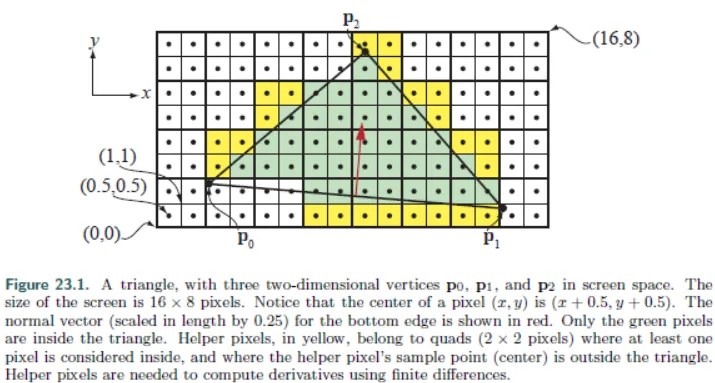
The pixels drawn multiple times within a quad constitute quad overdraw. The larger the area of a triangle, the smaller the proportion of quad overdraw. In extreme cases, if a triangle occupies only 1 pixel, then 3 pixels will be drawn unnecessarily, resulting in 75% quad overdraw.
The implementation logic of quad overdraw in GPUs is divergency. Therefore, in Adreno architectures, which are more sensitive to divergency, this issue becomes more severe. An Adreno architecture can handle a maximum of 4 triangles per wave but has 128 fibers. In extreme cases, if each triangle occupies only 1 pixel, then 128 fibers only draw 4 effective pixels, wasting 96.9% of computational power.
Thus, we need to minimize the occurrence of small triangles, and the most direct way to achieve this is by using appropriate levels of detail (LOD). This will not only reduce the number of triangles drawn and bandwidth usage but also improve rendering efficiency. Arm recommends that each triangle should cover at least 10-20 fragments.
– Use models that create at least 10-20 fragments per primitive.
To verify quad overdraw, we can still use % Shader ALU Capacity Utilized and % Time ALUs Working metrics. The divergency ratio = % Time ALUs Working – % Shader ALU Capacity Utilized
To eliminate the interference caused by shader branching, we can replace shaders with simple shaders that have no branches.
Shader Complexity
When we talk about “shader complexity,” we refer to:
1. The number of static instructions in the shader.
2. The number of dynamic instructions in the shader.
3. The number of registers used by the shader.
Let’s discuss the issues that arise when these metrics are excessive.
Instruction Count
“Instruction count” is divided into static instruction count and dynamic instruction count. The static instruction count refers to the number of instructions in the compiled shader program, while the dynamic instruction count refers to the number of instructions executed. For example, using [unroll] to unroll a for loop will increase the static instruction count compared to a non-unrolled version. However, regardless of whether it is unrolled, the dynamic instruction count for both programs should be the same.
Offline compilers report static instruction counts, but they may also report the dynamic instruction count for the shortest execution path.
When the static instruction count is too high, the cache may become insufficient. The Snapdragon Profiler has a corresponding metric:
% Instruction Cache Miss: Do not let the shader (after compilation) exceed 2000 instructions (VS+PS). You can see the instruction count using the SDP Offline Compiler.
Register Count
Shader Processors (SPs) use registers to store the context of shaders. If a shader uses too many registers, when switching to another shader to hide latency, there may not be enough registers to switch, leading to decreased execution efficiency.
What is “Hide Latency”? It refers to the situation where, when an SP is executing a shader that experiences long latency (such as texture sampling), to improve utilization, the SP switches to another shader instead of waiting. This is called “Hide Latency.” The condition for a successful switch is whether the registers can accommodate the context of the new shader while retaining the context of the original shader. If a shader requires many registers and the current registers are insufficient, the switch will fail.
Texture sampling and Storage Buffer access can cause latency, and the number of registers used affects the efficiency of hiding latency. Therefore, we should avoid shaders that simultaneously require many texture samples and have complex calculations (high register usage).
As the number of registers continues to increase and exceeds the size of on-chip memory, “Register Spilling” occurs. This means that registers cannot be stored and must be placed in system memory, leading to a dramatic drop in performance.
The number of registers is a significant difference between mobile and desktop GPUs. Snapdragon 888 has 64KB per 64 ALUs, while NVIDIA/AMD has 256KB per 64 ALUs. This directly determines the complexity of shaders on both platforms. Running desktop shaders on mobile will not result in a linear performance drop due to instruction count but will be significantly affected by insufficient register capacity, leading to inefficient execution and even spilling.
Use the Offline Compiler’s register footprint per shader instance to check the register usage of shaders.
In the Snapdragon Profiler, you can assess shader execution efficiency through % Shader Stalled. When the SP cannot switch to another shader for execution, stalls occur.
% Shader Stalled: The proportion of cycles in which no execution units (mainly ALU, texture & load/store) are working out of the total cycles. Memory fetch stalls do not necessarily mean Shader Stalled, as if the shader can still find a wave to execute ALU, it does not count as a stall. % Shader Stalled indicates a decrease in IPC (instructions per cycle).
Vertex Shader is Performance Sensitive
On mobile devices, vertex shaders are performance-sensitive for several reasons:
First, in TBR architecture, triangles that cross tiles are executed in each tile. If MSAA is enabled, the tile size becomes smaller, increasing the number of triangles that cross tiles, thus increasing the pressure on the VS.
Second, as mentioned in the architecture section, in Adreno/Mali architectures, the VS is executed twice. In iOS, the VS is only executed once during the binning pass, with only the PS executed during the render pass.
In Adreno/Mali, the Binning Pass does not execute the full VS but only the instructions related to position. Generally, position calculations only require coordinate transformations. However, if complex calculations or texture sampling are involved, this overhead is magnified. For example, calculating vertex positions through height map sampling during terrain rendering.
Third, Vertex Output also affects pipeline execution efficiency, which is related to hardware implementation.
In the Adreno architecture, vertex output does not need to resolve to SYSMEM. Each SP has a small area in its Local Buffer for storing VS output, which can be used in the PS stage. However, this area is limited; in the 8Gen2, it is only 8KB. If this area in the SP is full, VS stalls will occur. If a VS output consists of 12 float4 attributes, then 8KB can accommodate 64 fragments.
In Mali’s fifth-generation GPU architecture, prior to Immortalis, the VS output generated during the render pass would resolve to SYSMEM and be read back during the PS. This resulted in bandwidth consumption. The fifth-generation GPU architecture introduced Deferred Vertex Shading (DVS), which eliminates the need for VS output resolve/unresolve, significantly improving bandwidth. The official claim is a 20% – 40% bandwidth improvement. However, it can be imagined that this part also has storage limits.
In summary:
1. Enabling MSAA increases the pressure on the VS.
2. Avoid heavy logic in the position calculation part of the VS, especially avoid data fetch and texture sampling.
3. Control the data volume of VS Output; excessive data may cause VS stalls; for older Mali models and iOS, it will increase bandwidth usage.
Should PrePass Be Done?
This question is relatively complex.
Let’s revisit the Adreno architecture diagram: During the Binning Pass, LRZ (Low Resolution Z) elimination is performed. Then, during the Rendering Pass, early-z and late-z are executed. The LRZ Test performs low-resolution, primitive-level depth elimination, while Early-Z and Late-Z perform full-resolution, quad-level depth elimination.
For opaque objects, different granularity tests and writes are performed during the LRZ/Early-Z stages; no further testing is needed during Late-Z.
For translucent (alpha blend) objects, writing is not allowed. However, since they may be eliminated by closer depths, testing is permitted.
For mask (alpha test) objects, depth can actually be determined during the VS stage, but since they may be discarded during the PS stage, they can only be tested during LRZ and Early-Z, and writing can only occur during Late-Z.
For custom depth (oDepth) objects, depth is only written during Late-Z and will not be depth-culled. oDepth is the pixel shader output depth register, specifically for writing depth in the PS stage.

With the above organization, let’s revisit this myth.
PrePass, in traditional desktop practices, involves running a simpler shader for opaque objects to generate a depth map for subsequent BasePass use, aiming to reduce overdraw. However, for mobile devices, since the LRZ in the binning pass has already performed a similar function, it is unnecessary for opaque objects on mobile devices.
The discussion on whether to perform PrePass on mobile devices generally focuses on mask objects. Mask objects cannot write depth during LRZ/Early-Z, which can lead to overdraw for large mask objects. If many mask objects are interspersed (such as vegetation), the overhead can be similar to rendering a bunch of transparent objects.
Moreover, the impact of masks varies across architectures.
In PowerVR architecture, “Overdraw Reducing” uses HSR (Hidden Surface Removal). This is a fragment-level visibility elimination that outputs a full-resolution visibility map during the binning pass, allowing the render pass to execute the PS without needing to execute the VS again. Therefore, the draw call submission order can be ignored.
With PowerVR TBDR, Hidden Surface Removal (HSR) will completely remove overdraw regardless of draw call submission order.
However, if alpha testing is involved, it becomes problematic. The true depth must be obtained after the PS execution before feedback can be provided to HSR. It is unclear from the documentation whether this feedback will stall subsequent draw calls. Since the render pass relies on the visibility map generated by HSR, it can be inferred that even if it does not stall subsequent draw calls, it may stall the entire HSR.
For Adreno/Mali architectures, while masks do not cause pipeline stalls, rendering passes mixed with opaque and mask objects still impact pipeline execution efficiency. Therefore, it is also recommended to render opaque and mask objects as two separate passes.
The default handling scheme is to render opaque and mask objects in two separate passes to avoid masking blocking the rendering pipeline.
On top of the default scheme, it may be considered to use specialized simplified VS/PS to perform a PrePass for mask objects, allowing them to be marked as Depth Test Equal during the BasePass without needing to be marked as Alpha Test. Since mask objects require PS execution to obtain depth, a specialized PS that only samples alpha is needed.
In summary, the significance of the PrePass for masks lies in using a batch of simple draw calls to improve BasePass pipeline execution efficiency and reduce overdraw.
In PowerVR architecture, alpha test late-z will not become a bottleneck for HSR; in Adreno/Mali architecture, there is no stall pass issue, and the PrePass is more significant in that it can help eliminate objects in the BasePass, whether opaque, translucent, or masked.
However, this batch of “simple draw calls” also incurs overhead, and whether PrePass is a positive optimization needs to be determined through performance tuning based on scene types and device models.
Running Compute Shaders Can More Efficiently Utilize the GPU
Currently, Shader Processors (SPs) are designed to be unified, meaning a single SP can execute VS/PS/CS, and there are no dedicated SPs for running CS. Therefore, running the raster pipeline separately does not lead to low hardware utilization. Moreover, when SPs operate under VS/PS and CS, they are in two different “working modes.” The switching cost varies depending on the hardware.
If VS/PS and CS can run “simultaneously” on the same SP, this feature is called Async Compute. This “simultaneously” is in quotes, meaning that there can be graphics waves and compute waves switching on the SP to hide latency. In this regard, it can indeed utilize the GPU more efficiently.
However, for graphics and compute running together, it is best if their resource usage is complementary. For example, good matches include:
• Graphics: Shadow Rendering (Geometry limited)
• Compute: Light Culling (ALU Heavy)
Poor matches include:
• Graphics: G-Buffer (Bandwidth limited)
• Compute: SSAO (Bandwidth limited)
Currently, iOS has the best support for Async Compute on mobile devices. Mali also supports it, but more details need testing. However, Adreno does not support it as of now.
Technical Limitations of GPU Driven on Mobile
GPU Driven is a very fine-grained triangle culling + batching scheme on desktop, but it is rarely applied on mobile. Although its purpose is to “exchange GPU performance for CPU performance,” the performance impact on GPUs and the optimization on CPUs do not match on mobile.
The main reasons are twofold:
• Inefficient random access to Storage Buffers
• A large number of small draw calls and invalid draw calls with instanceCount=0
In GPU Driven, the “PerInstance” vertex stream contains indices pointing to various storage buffers. These storage buffers store instance transforms, material data, primitive data, etc. In the VS, these storage buffers are accessed via indices. Originally, this data was obtained through instance buffers (vertex streams) or uniform buffers, which could be quickly accessed in on-chip memory. After switching to storage buffers, these buffers are generally large, and on-chip memory and L1/L2 cannot accommodate them, leading to low efficiency as they often need to access SYSMEM.
Especially for instance transforms, which participate in VS position calculations, this leads to the need to run this part of the calculation twice on mobile.
True GPU Driven performs cluster-level culling, where a cluster may consist of 64/128 triangles. Each cluster is drawn as a sub-draw call of an indirect draw call. If this cluster is culled, the instance count for this sub-draw call will be set to 0. This approach generates a large number of small draw calls and many instanceCount=0 invalid draw calls.
GPUs have dedicated components for generating waves; Adreno’s is called HLSQ (High Level Sequencer), and Mali’s is called Warp Manager. These components pre-read several draw calls to generate waves for mutual switching. However, the number of draw calls that can be pre-read on mobile is limited; for example, Adreno 8Gen1’s HLSQ can only pre-read 4 draw calls. If these are small or invalid draw calls, it leads to underfeeding the backend pipeline.
Conclusion
The way to debunk myths is to discard mysticism and understand the underlying principles. I hope this can provide clearer ideas and methods for our future optimizations, rather than blindly feeling our way through.
By applying the Feynman learning method, this serves as a summary of my personal knowledge in this area.
However, as an application layer, we can only explore and speculate outside the black box constructed by manufacturers. Therefore, there will inevitably be many inaccuracies, incompleteness, and outdated information. I hope for your understanding.

// Reference
【1】AI and Memory Wall.
https://medium.com/riselab/ai-and-memory-wall-2cb4265cb0b8
【2】Arm GPU Best Practices Developer Guide | Triangle density.
https://developer.arm.com/documentation/101897/0302/Vertex-shading/Triangle-density
【3】Arm GPUs built on new 5th Generation GPU architecture to redefine visual computing.
https://community.arm.com/arm-community-blogs/b/announcements/posts/arm-gpus-built-on-new-fifth-gen-architecture
【4】A close look at the Arm Immortalis-G720 and its 5th Gen graphics.
https://www.androidauthority.com/arm-immortalis-g720-gpu-deep-dive-3328658/
【5】Arm Community (2013) Killing Pixels – A New Optimization for Shading on ARM Mali GPUs.
https://community.arm.com/arm-community-blogs/b/graphics-gaming-and-vr-blog/posts/killing-pixels—a-new-optimization-for-shading-on-arm-mali-gpus.
【6】Arm Community (2019) Immersive experiences with mainstream Arm Mali-G57 GPU.
https://community.arm.com/arm-community-blogs/b/graphics-gaming-and-vr-blog/posts/arm-mali-g57-gpu.
【7】Arm Developer Documentation (no date a) Arm Mali Offline Compiler User Guide.
https://developer.arm.com/documentation/101863/0801/Using-Mali-Offline-Compiler/Performance-analysis/IDVS-shader-variants.
【8】Arm Developer Documentation (no date b) Arm Mali Offline Compiler User Guide – Mali GPU pipelines.
https://developer.arm.com/documentation/101863/0801/Mali-GPU-pipelines.
【9】ARM Tech Forum (2016) Bifrost – The GPU architecture for next five billion. (Accessed: October 26, 2023).
https://docplayer.net/90745896-bifrost-the-gpu-architecture-for-next-five-billion.html
【10】Beets, K. (2013) Understanding PowerVR Series5XT: PowerVR, TBDR and architecture efficiency – Imagination.
https://blog.imaginationtech.com/understanding-powervr-series5xt-powervr-tbdr-and-architecture-efficiency-part-4/
【11】Davies, J. (no date) The Bifrost GPU architecture and the ARM Mali-G71 GPU.
https://community.arm.com/cfs-file/__key/telligent-evolution-components-attachments/01-2066-00-00-00-00-71-76/HotChips-Presentation-Jem-Davies.pdf.
【12】Frumusanu, A. (2019) Arm’s new Mali-G77 & Valhall GPU architecture: a major leap.
https://www.anandtech.com/show/14385/arm-announces-malig77-gpu.
【13】GPU Framebuffer Memory: Understanding Tiling | Samsung Developers (no date).
https://developer.samsung.com/galaxy-gamedev/resources/articles/gpu-framebuffer.html.
【14】Hidden surface removal efficiency (no date). (Accessed: October 7, 2023).
https://docs.imgtec.com/starter-guides/powervr-architecture/html/topics/hidden-surface-removal-efficiency.html
【15】Improved culling for tiled and clustered rendering in Call of Duty: Infinite Warfare (2017).
https://research.activision.com/publications/archives/improved-culling-for-tiled-and-clustered-rendering-in-call-of-dutyinfinite-warfare.
【16】Life of a triangle – NVIDIA’s logical pipeline (2021).
https://developer.nvidia.com/content/life-triangle-nvidias-logical-pipeline.
【17】Mei, X., Wang, Q. and Chu, X. (2017) ‘A survey and measurement study of GPU DVFS on energy conservation,‘ Digital Communications and Networks, 3(2), pp. 89–100.
https://doi.org/10.1016/j.dcan.2016.10.001.
【18】PowerVR Developer Community Forums (2015) Alpha Test VS Alpha Blend
https://forums.imgtec.com/t/alpha-test-vs-alpha-blend/2291/2.
【19】Qualcomm® AdrenoTM GPU Overview (2021). (Accessed: October 7, 2023).
https://developer.qualcomm.com/sites/default/files/docs/adreno-gpu/snapdragon-game-toolkit/gdg/gpu/overview.html
【20】Qualcomm® SnapdragonTM Mobile Platform OpenCL General Programming and Optimization (2023). (Accessed: September 16, 2023).
https://developer.qualcomm.com/qfile/33472/80-nb295-11_a.pdf
【21】Understanding and resolving Graphics Memory Loads (2021). (Accessed: October 7, 2023).
https://developer.qualcomm.com/sites/default/files/docs/adreno-gpu/snapdragon-game-toolkit/gdg/tutorials/android/gmem_loads.html
【21】Wu, O. (no date) Mali GPU Architecture and Mobile Studio.
https://admin.jlb.kr/upload/abstract/190007/259.pdf.
【22】Mobile GPU Architecture | wingstone’s blog (2020).
https://wingstone.github.io/posts/2020-09-17-mobile-gpu-architecture/