Review of Previous Content
DDR Configuration of RZ/G2L
DDR Configuration of Renesas RZ/G2L MPU (1)
DDR Configuration of Renesas RZ/G2L MPU (2)
3.2
Preparation Before Use
Before using the configuration tool, the following preparations are required:
-
Thoroughly understand the hardware information, including the model, capacity, speed, and data width of the #DDR chips, as well as the connection method and pin definitions of the DDR chips to the processor in the schematic. This information is the basis for accurate configuration and directly affects the performance and stability of the memory.
-
Ensure that Excel software supporting macro functions is installed, as the configuration tool is developed based on Excel macros and requires macros to be enabled to function properly. Also, obtain the latest version of the configuration tool and familiarize yourself with the various tables and parameters of the tool.
3.3
Specific Steps for Use
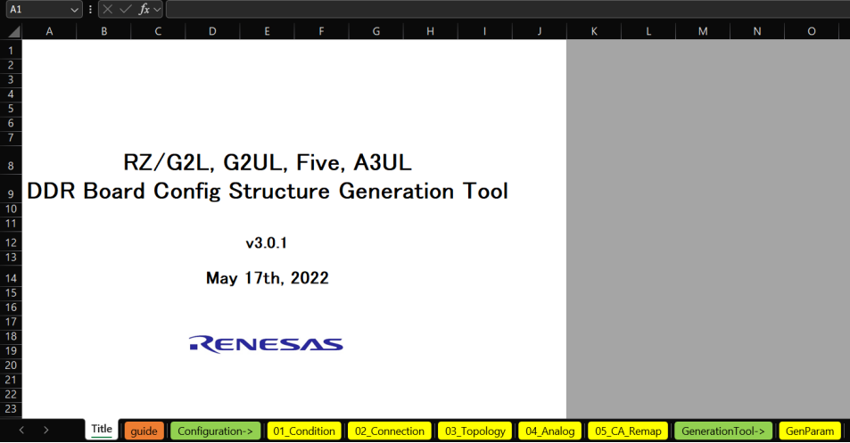
This is the interface of the configuration tool. The orange guide table provides an explanation of the DDR configuration process implemented in trusted-firmware-a. The green table can be ignored, while the yellow tables 01_Condition, 02_Connection, and 03_Topology generally do not need to be modified. They list the parameter options, connection methods, and topology combinations for various DDR chip models. The yellow table 04_Analog defines various Connection#/Condition# and Topology# matching impedance and other hardware parameter configurations. It is generally not recommended for software personnel to modify these. Software personnel typically need to modify the 05_CA_Remap table and the GenParam table.
3.3.1
Selection of 01_Condition and 02_Connection Tables
Taking the RZ/G2L SMARC EVK as an example, it is connected to a single 1G*16bit DDR4 (MT40A1G16KD – 062E: E).
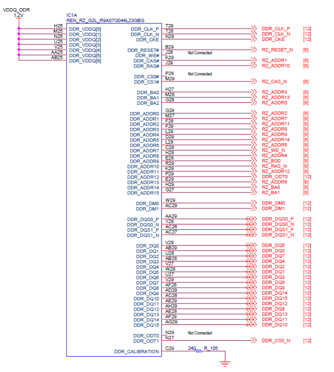
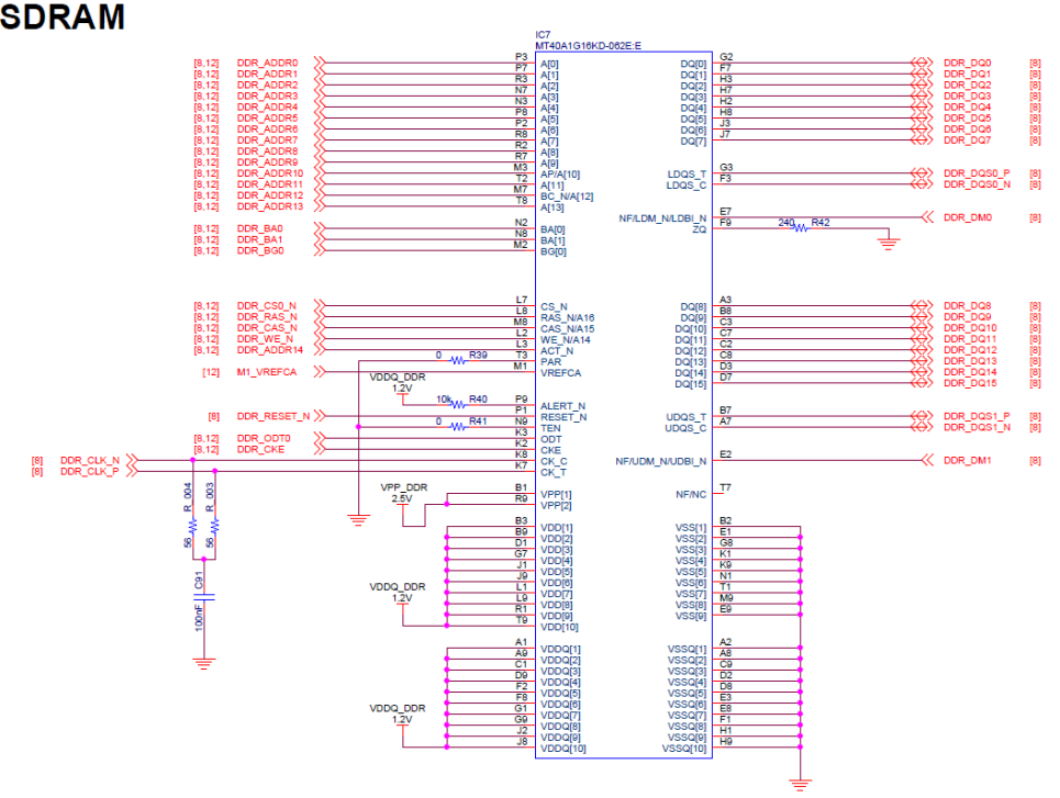
First, find the corresponding options for the DDR chip and the schematic connection from the configuration tool’s 01_Condition and 02_Connection tables. In the 01_Condition table, select the appropriate condition option based on the specifications provided in the datasheet of the DDR chip MT40A1G16KD – 062E: E, such as D4 – 01 – 1; in the 02_Connection table, determine the corresponding connection option based on the connection method in the schematic and relevant PCB information, such as C – 011.
3.3.2
Selection of 03_Topology Table
Based on the information determined in the previous step and the DDR4 chip model, find the corresponding topology option from the configuration tool’s 03_Topology table. In the 03_Topology table, determine the corresponding topology type T – 1bc by searching for the row and column that match the DDR chip parameters (based on the key information in columns C, H, J, AB, AI, AJ). The choice of topology type determines the key configurations such as memory address mapping and signal connections, which are crucial for the normal operation of the memory.
3.3.3
Operation of 05_CA_Remap Table
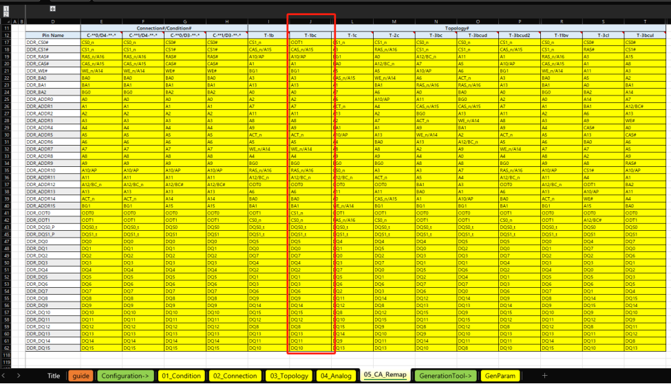
Open the 05_CA_Remap table of the configuration tool, select the column corresponding to the topology type determined in the previous step (e.g., column J T – 1bc), and then complete the pin assignment operation based on the schematic. During the pin assignment process, it is necessary to accurately map the processor-side pins to the DDR chip-side pins.
Here is a practical tip:
In the schematic, there are three pins on the SoC side (DDR_CS0/DDR_ODT0/DDR_WE) that are not exposed, and there are also three options (DDR_CS1/DDR_ODT1/DDR_BG1) in the dropdown options for pin assignment that do not exist on the DDR chip side. Therefore, these three pins on the SoC side can be freely selected from these three options in the dropdown, as long as they are not repeated.
3.3.4
Operation of GenParam Table
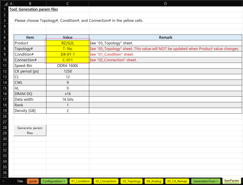
Open the GenParam table of the configuration tool, select RZ/G2L from the dropdown options in row 7 (Product), select the previously determined T – 1bc in row 8 (Topology#), select D4-01-1 in row 9 (Condition#), and select C-011 in row 10 (Connection#). Other related parameters, such as Speed – Bin (DDR4 – 1600L), CK period [ps] (1250), CL (12), CWL (9), AL (0), etc., will be automatically filled based on the previous selections and do not need to be manually configured.
3.3.5
Generating Configuration Files
After completing all parameter settings in the GenParam table, click the Generate param button to generate the configuration files param_mc.c and param_swizzle.c. The generated files need to be renamed according to the rules mentioned earlier for correct usage in subsequent development.
3.3.6
Using Configuration Files
The configuration files param_mc.c and param_swizzle.c generated by the configuration tool are used in the flash-writer and trusted-firmware-a source code projects for RZ/G2L. The methods provided in the guide table of the configuration tool target the trusted-firmware-a source code project. You can also refer to RZ BSP Porting – ARM Trusted Firmware – Renesas-wiki – Renesas Confluence for more information. The usage of the DDR configuration files in the flash-writer source code project can be referenced in RZ BSP Porting – Flash Writer – Renesas-wiki – Renesas Confluence(You can copy the link below to your browser or scan the QR code to view).
RZ BSP Porting – ARM Trusted Firmware – Renesas-wiki – Renesas Confluence
https://confluence.renesas.com/display/REN/RZ+BSP+Porting+-+ARM+Trusted+Firmware

RZ BSP Porting – Flash Writer – Renesas-wiki – Renesas Confluence
https://confluence.renesas.com/display/REN/RZ+BSP+Porting+-+Flash+Writer

3.4
Usage Tips and Precautions
During pin assignment, the naming of the connections in the schematic may not correspond one-to-one with the pin naming on the SoC side or the DDR chip. This is a challenge in the configuration process. It is necessary to carefully analyze the schematic, using logical thinking and spatial imagination to accurately identify the connection relationships between the DDR chip and the SoC side pins.
The tables 01_Condition, 02_Connection, and 03_Topology in the configuration tool generally do not need to be modified; they are pre-set based on hardware and memory standards. The 04_Analog table is mainly for reference by PCB designers, and any modifications should be suggested by PCB design engineers based on hardware design.
When filling in the parameters in the GenParam table, ensure the accuracy of the parameters, as these directly affect the performance and stability of the DDR memory. Incorrect parameter settings may lead to memory malfunction or performance degradation.
Summary
This article comprehensively introduces the support of RZ/G2L for DDR3L and DDR4, delves into the technical details and differences of DDR3, DDR4, and DDR3L, and elaborates on the usage process of the RZ/G2L DDR configuration tool. By understanding these contents, embedded software engineers can better grasp the DDR adaptation work for RZ/G2L.
For more detailed usage methods, please refer to the following websites:
Renesas Official Website
https://www.renesas.cn/cn/zh/products/microcontrollers-microprocessors/rz-mpus/rzg2l-getting-started

RZ Product WIKI Website
https://renesas.info/wiki/Main_Page



Need Technical Support?
If you have any questions while using Renesas MCU/MPU products, you can scan the QR code below or copy the URL into your browser to enter the Renesas Technical Forum to find answers or get online technical support.

https://community-ja.renesas.com/zh/forums-groups/mcu-mpu/
1
END
1
Recommended Reading
Product Overview | RZ/G2 Series MPU

New Product Launch | Renesas Ecosystem Partner Mill Electronics Launches RZ/G2UL Core Board to Support Industry 4.0 Development!

Open Registration | 2025 Renesas RA MCU Online Summit