Word count: 821, reading time approximately 5 minutes
PDM (Pulse Density Modulation) is an interface commonly used to connect digital microphones, which have become a standard peripheral in modern electronic devices. It can be considered an essential interface in SoC chips. First, let’s understand the timing of the PDM interface.
1 Interface Timing
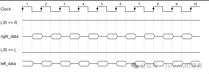
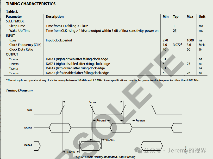
The digital microphone acts as a slave and requires a clock to operate, similar to a slave sending mode SPI interface. The PDM interface serves as the master receiving PDM interface. The digital microphone generally follows the timing of the interface shown above, which includes a clock (provided by the PDM interface) and an L/R signal to distinguish whether data is sent on the rising or falling edge. When L/R is high, data is sent on the falling edge; when L/R is low, data is sent on the rising edge. Typically, the right channel data is sent on the falling edge and the left channel data on the rising edge. A single data line is used, and the data from a digital microphone is valid only between the rising and falling edges, allowing a single data line to receive dual-channel data.
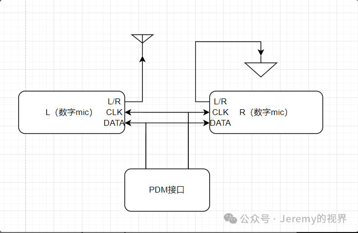
Dual-channel connection:
2 Advantages and Disadvantages
2.1 Fewer IOs
From the above interface timing, it can be seen that PDM requires a maximum of only 2 IOs to complete communication in dual-channel mode, significantly reducing the number of IOs needed for communication.
2.2 High Performance
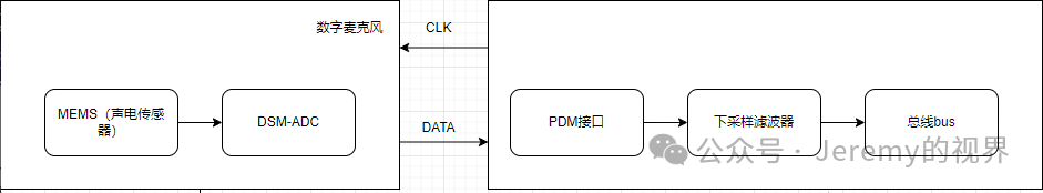
The digital microphone actually uses an interface based on DSM (Delta-Sigma Modulation). DSM modulation primarily achieves performance through high oversampling rates and noise shaping. The main internal structure is shown in the figure below.
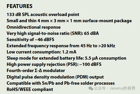
The process of DSM modulation is somewhat complex, but the following formulas can be used to design the subsequent down-sampling filter for the PDM interface to meet the requirements: Oversampling (yes) + Noise shaping (no), oversampling rate = , performance improvement = Oversampling (yes) + Noise shaping (1st order), oversampling rate = , performance improvement = Oversampling (yes) + Noise shaping (2nd order), oversampling rate = , performance improvement = Oversampling (yes) + Noise shaping (3rd order), oversampling rate = , performance improvement = Oversampling (yes) + Noise shaping (4th order), oversampling rate = , performance improvement = Generally, DSM modulation will only achieve up to 4th order; beyond that, there is little benefit. Here is a specification sheet for a digital microphone, ADI’s ADMP621.
3 Post-Processing
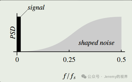
Generally, after the PDM interface, the PDM signal needs to be converted back to a PCM signal, which requires a digital filter to complete this process. The output signal power spectrum of the digital microphone is shown below, and we need to design a digital filter based on our bandwidth to filter out the noise shaping portion.
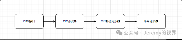
Generally, the oversampling rate will be quite high, so multi-stage filters are needed (single-stage down-sampling filters have high orders, making them difficult to implement in actual chips). We can use CIC + CIC compensation filter + half-band filter to achieve this down-sampling process, depending on the specific situation to determine if a half-band filter is necessary.
Feel free to add me on WeChat: Jeremy3141592654 for discussions, and don’t forget to follow!
Previous articles:Creating Your Own Chip (3) – IIS SectionIn 1997, at 28 years old, where should an IC engineer go?