This LED project features an interactive LED display wall controlled by Arduino and assembled with a 3D printed casing.
The overall project is not expensive and has strong human-computer interaction, hoping to inspire you.
Materials List
-
Arduino Mega×1 -
WS2812b addressable LED strip×several -
Tactile switch×64 -
5V 10A power supply×several -
18 gauge wire×several -
White PLA filament×several -
4’x 4’x 1/4” MDF×several -
Solder×several -
Hot glue×several
3D Printed Wall Sections
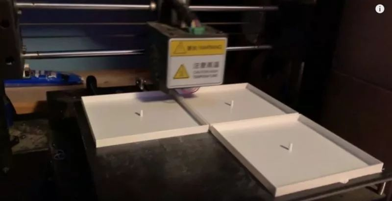
This section requires 3D printing 64 pieces of 8×8 grid. Each wall block is a 3.6-inch square with a thickness of 1 inch. The edges of the wall will have some notches to facilitate wiring for the LED strips and buttons. Printing three blocks at a time takes about 5.5 hours. Completing all takes approximately 120 hours.
So while printing, you can simultaneously work on other parts.
All 3D printed STL files:
<span>https://www.thingiverse.com/thing:4080834</span>
Or you can download the package at the end of the article.
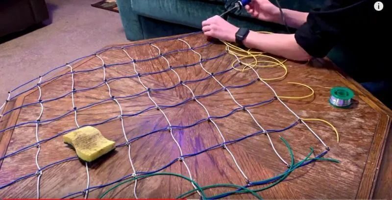
Wiring the LED Strips
WS2812b LED strips are used because they are individually addressable, allowing each LED on the strip to be programmed with different colors and brightness. They can also pass data from one pixel to the next. These features can be achieved with a single data pin from the Arduino. The pixel density of the strip is thirty LEDs per meter.
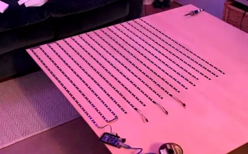
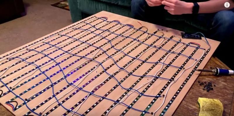
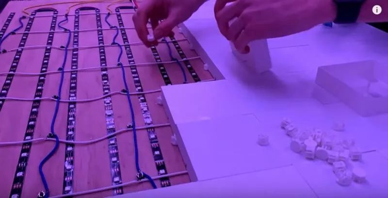
Each wall block installs six LEDs, three in a row, for two rows. Therefore, we cut these strips into sixteen segments, each with twenty-four LEDs. Then we glue these strips to the wooden board. Be sure to clean the board before securing the strips.
Also, pay attention to the direction of the LED strip installation. As shown in the image, start from the bottom left corner of the board, and change direction after completing one side. Solder the output of each strip to the input of the next strip.
Adjusting the Size of the Circuit Board (Optional)
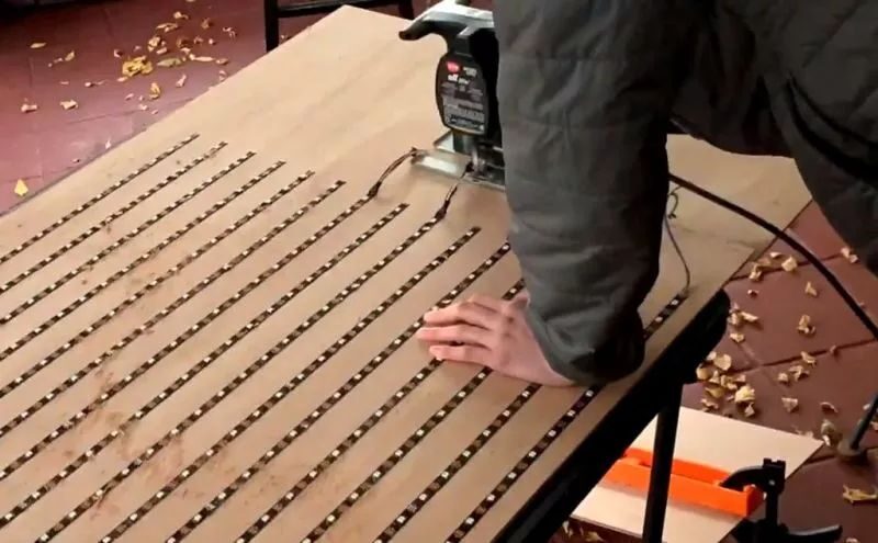
The wood board we bought is four inches, but we found that only three inches are needed, so we need to saw off the excess material. However, if you want to make a larger display wall, you just need to add more 3.6-inch wall blocks.
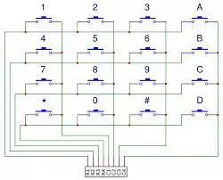
Making the Button Matrix
This part is not only time-consuming but also requires patience. In this section, we will use the keyboard library included in the Arduino IDE to connect the 64 buttons in rows and columns. The image shows a 4×4 example; increase to an 8×8 grid following this structure, or you can choose your own matrix size.
1. Prepare sixteen wires, each 3.6 inches long with stripped ends, to install the buttons in the center of each wall block.
2. Solder one leg of each tactile switch to the row (horizontal) wire. Solder the column (vertical) wire to the diagonal of the row wire. When the tactile switch is pressed, it will connect the horizontal and vertical wires together.
3. Each row and each column needs a wire to connect to the digital pins of the Arduino. Color code each wire to facilitate troubleshooting; during checks, I also changed pins several times.
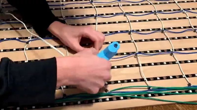
4. Glue all the buttons to the wooden board. Ensure each button is securely fixed in place.
Testing the Circuit
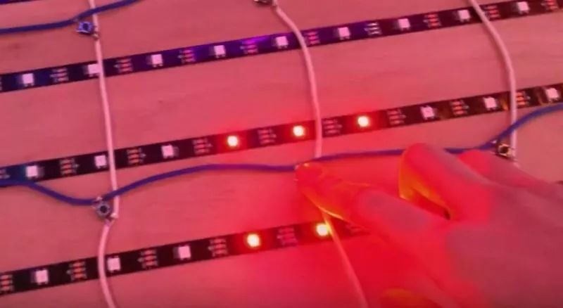
Once all the LED strips and buttons are installed, you can start testing.
In the code, there are functions to test the LED strips and buttons. If there are any issues, you can discover and solve them in a timely manner. Be sure to troubleshoot as much as possible before adding wall blocks.
Installing the 3D Wall Sections
1. To connect the blocks to the wooden board, a 3D printed bracket is designed to secure the adjacent four blocks at each corner. Glue one block at a time, and slowly connect them, ensuring each block is tightly next to each other without leaving excess space.
2. Additionally, print 64 spacers and glue them to the plunger of each block. These spacers can compensate for the height increase due to the bracket and also provide space for the click plungers, compensating for slight errors in button spacing.
The STL files for the brackets and spacers can be downloaded at the end of the article.
Programming
So far, the hardware part is complete, and we can start programming! Currently programmed are the rainbow pattern mode and click painting mode. You can see the specific effects in the video.
▲ Click to watch the complete video
Download the code from the project repository:
<span>https://github.com/TechRandom/Interactive-LED-Wall/blob/master/LED_Wall_main.ino</span>
You can also modify the code to dynamically display custom visual effects.
Future Possible Features
1. Audio visualizer using microphone and FFT Arduino library.
2. Designable games (checkers, tic-tac-toe, battleship, go).
3. Memory function.
4. More games playable on the grid.

How did second-tier university students succeed in autumn recruitment under the “cold winter”?

What is a GPU? What is the relationship between GPU and graphics card? What is the layout of domestic GPU?

Blue Bridge Cup, reached the finals

What I have seen and learned during five months at Huawei!
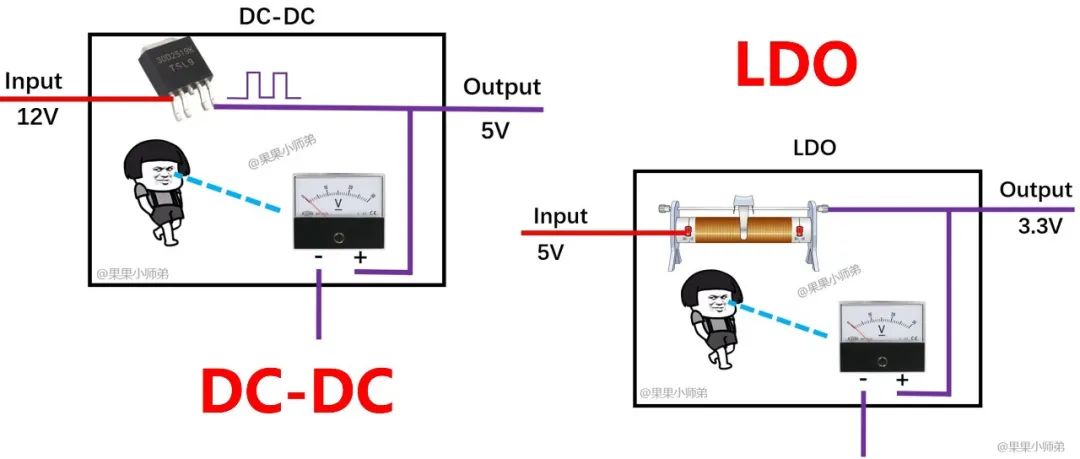
About LDO and DC-DC, this article is enough!