One


ARM Assembly
Generally, our computers are X86 architecture machines. Here we use clang to compile our files. Compiling files by ourselves and using IDA to learn alongside makes it easier to understand.
Two


Some instructions about clang:
Using clang to directly compile into an executable file
// Compile our file into ARMv5 architecture file (32-bit)
clang -target armv-linux-android21 demo.c -o demo
// Compile our file into ARMv7-A architecture file (32-bit)
clang -target armv7a-linux-android21 demo.c -o demo
// Compile our file into AArch64 architecture file (64-bit)
clang -target aarch64-linux-android21 1.cpp -o demo
Compile in separate steps
Preprocessing
clang -target arm-linux-android21 -E demo.c -o demo.i
Compilation (generate assembly file)
clang -target arm-linux-android21eabi -S demo.i -o demo.s
Assembly (generate unrelocated binary file)
clang -target arm-linux-android21eabi -S demo.s -o demo.o
Linking (generate executable file)
clang -target arm-linux-android21eabi -S demo.o -o demo
Clang compiling thumb architecture files
clang -target arm-linux-android21 -S -mthumb demo.c -o demo.s
The difference between ARM and thumb
When we study ARM architecture, we often hear about switching from ARM state to thumb state. Here is a record of the background.
With the development of ARM architecture, it has been used in many areas. However, our ARM instruction set is either 32-bit or 64-bit. With the increasing demand for 32-bit processors in devices like smartphones, power consumption and cost have become critical. The issue of how to reduce program size is urgent. At this time, ARM company launched the ARM7TDMI processor, which supports a 16-bit instruction set, known as thumb. The purpose of thumb is to achieve higher code density, which is essentially an extension of our ARM instruction.
ARM processors have the ability to seamlessly switch between ARM state and Thumb state, allowing dynamic switching of instruction sets as needed.
Some differences:
In summary, thumb is an ARM instruction branch that achieves higher performance and higher code density.
Three


ARM Registers
Arm-v7 Architecture
ARM has a total of 37 registers, all of which are 32-bit long (specifics can be seen in the following working mode diagram).
Among the 37 registers, the first 31 (0~30) are general-purpose registers (used differently in different modes), and the last 2 (31,32) are special-purpose registers (<span>sp</span> register and <span>pc</span> register). 5 are fixed for use in 5 types of exception modes as SPSR.
◆ CPSR: Current Program Status Register, usually not directly operated unless for exception handling or task switching.
◆ SPSR: Used in exception handling, stores the CPSR value at the time of the exception.
General-purpose registers
The general-purpose registers of the ARM architecture are used to execute most instructions, and can store temporary data, addresses, and intermediate computation results.
R0-R12: General-purpose registers
◆ R0-R3 are usually used as instruction operands, passing function parameters and return values.
◆ R4-R11 are usually used for local variable storage, known as “callee-saved” registers, values need to be saved before function use and restored before return.
◆ R12 is sometimes referred to as Intra-Procedure-call scratch register (IP), used as temporary storage in certain function calling conventions. FP: Stack Frame Base Pointer Register, which is R12.
R13 (SP): Stack Pointer Register
◆ SP points to the current top of the stack, managing function call parameter passing, local variable storage, and return addresses.
R14 (LR): Link Register
◆ LR stores the return address of subroutine calls. When executing the BL (Branch and Link) instruction, the current value of PC is saved to LR, and after the function execution is complete, it returns to the calling point.
R15 (PC): Program Counter
◆ PC stores the address of the next instruction to be executed. When executing branch instructions, PC is updated to the new address.
CPSR (Current Program Status Register)
The CPSR register contains current program status information, including:
◆ Condition flags: Zero flag (Z), Negative flag (N), Carry flag (C), Overflow flag (V), usually set automatically after arithmetic or logical operations, used for conditional branch instructions.
◆ Control bits: Interrupt disable bit (I) and fast interrupt disable bit (F), used to control interrupt enable status.
◆ Mode bits: Indicate the current CPU operating mode, such as user mode, system mode, interrupt mode, etc.
SPSR (Saved Program Status Register)
When an exception occurs (such as an interrupt), the current CPSR is automatically saved to SPSR, so that the previous state can be restored after exception handling. Each exception mode has its own SPSR.
About ARM-V8 Architecture
General-purpose registers
The Arm-v8 architecture has 31 general-purpose registers X0-X30 (64-bit long), while the Arm-v7 architecture has only 16 general-purpose registers R0-R15 (32-bit long).
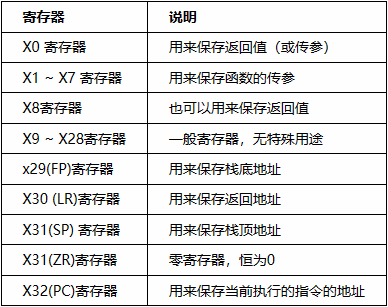
Special-purpose registers (X8, X16~X18, X29, X30): (Understand)
◆ X8: Indirect result register. Used to store the address of indirect results.
◆ Subroutine internal call registers, ip registers (Intra-Procedure-Call Temporary Registers), IP0 and IP1, can be used by Veneers (implementing Arm/Thumb state switching). Or used as temporary registers for storing intermediate values before subroutine calls. No need to save when used.
◆ x18: Platform register (Platform Register), used to store the ABI of the current platform.
◆ x29: Frame Pointer Register (FP), used to link stack frames, must be saved when used.
◆ x30: Link Register (LR), used to store the return address of subroutines.
Access methods for registers
Overall, there are two different usages for 64 registers: one is to access them as original 64-bit registers, and the other is to split the 64-bit registers into 32-bit registers for compatibility.
There are 2 ways to access general-purpose registers:
<span>W0</span> ~ <span>W30</span> to reference them. (Data is stored in the lower 32 bits of the register).<span>X0</span> ~ <span>X30</span> to reference them.For some special-purpose registers, the access methods are:
Stack Frame Pointer Register: 32-bit, referenced using <span>WSP</span>, 64-bit, referenced using <span>SP</span>.
Zero Register: 32-bit, referenced using <span>WZR</span>, 64-bit, referenced using <span>ZR</span>.
Four


Several working modes of ARM processors
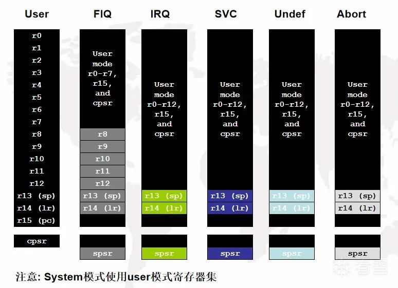
User Mode:
The default mode for normal program execution.
Fast Interrupt Mode (FIQ Mode)
Used for handling fast interrupt requests, with additional registers to reduce the execution time of the interrupt service routine.
Normal Interrupt Mode (IRQ Mode)
Used for handling normal interrupt requests.
Supervisor Mode
Used for kernel-level operations of the operating system, usually entered during system startup or system calls.
Undefined Mode
Entered when an undefined instruction is executed. When an exception or interrupt occurs, the processor automatically switches to the corresponding mode and uses the register set for that mode.
Abort Mode
Entered when a data or instruction prefetch abort occurs.
System Mode
Used to run kernel code of the operating system, sharing the same registers as user mode.
Five


Function calling conventions under ARM architecture
Common function calling conventions under ARM architecture are as follows:
AAPCS (ARM Architecture Procedure Call Standard)
AAPCS-VFP (ARM Architecture Procedure Call Standard with the Vector Floating-Point extension)
AAPCS:
AAPCS is the default function calling convention for ARM architecture, applicable to most ARM architecture compilers and operating systems. It defines the method of passing function parameters, stack usage rules, and register allocation methods.
AAPCS-VFP:
AAPCS-VFP is a function calling convention that adds the Vector Floating-Point extension based on AAPCS. It is applicable to functions that require floating-point operations.
Six


Assembly Instructions
Addressing modes in ARM:
Register Addressing
Move the value in R2 to R1.
mov r1, r2
Immediate Addressing
Move the immediate value 0xFF00 to R0.
mov r0, #0xFF00
Register Shift Addressing
Move the result of shifting R1 left by 3 bits to R0.
mov r0, r1, lsl #3
Register Indirect Addressing
Load the value pointed to by R2 into R1.
ldr r1, [r2] //r1=*r2
Base Plus Offset Addressing
Load the value at the address obtained by adding 4 to R2 into R1.
ldr r1, [r2, #4] ; r1=*(r2+4)
Multiple Register Addressing
Load the value in R1 into R2-R7 and R12, then add 32 to R1.
ldmia r1!, {r2-r7, r12}
Stack Addressing
Store the values of R2-R7 and LR into the stack, then subtract 24 from SP.
stmfd sp!, {r2-r7, lr}
Relative Addressing
If the condition code is EQ, jump to the label flag.
beq flag
flag:
Common Assembly Instructions
Branch Instructions
B: Unconditional branch
B label // Unconditionally jump to the label label
BL: Branch with link, stores the return address in LR register
BL label // Jump to the label label, and store the return address in LR
BLX: Branch with link and switch state instruction arm → thumb
BLX label // Jump to the label label, and store the return address in LR. Can switch between ARM and Thumb
Bx: Branch with state
BX R1 // Jump to the address stored in R1, and switch to the corresponding instruction set mode
Data Processing Instructions
mov: Assignment
MOV R0, R1 // Assign the value in R1 to R0.
ADD: Addition
ADD R0, R1, R2 // Add the values in R1 and R2, then store the result in R0.
SUB: Subtraction
SUB R0, R1, R2 //
AND: Bitwise AND
AND R0, R1, R2 // Perform a bitwise AND operation on the values in R1 and R2, then store the result in R0.
EOR: Bitwise XOR
EOR R0, R1, R2 // Perform a bitwise XOR operation on the values in R1 and R2, then store the result in R0.
ORR: Bitwise OR
ORR R0, R1, R2 // Perform a bitwise OR operation on the values in R1 and R2, then store the result in R0.
BIC: Bit Clear operation
BIC R0, R1, #0xf  // Perform a bitwise AND NOT operation between R1 and the immediate value #0xf, then store the result in R0.

// Clear the low 4 bits of R1
Multiplication Instructions:
MUL: General multiplication:
MUL r0 r1,r2 // r0 = r1 * r2 Multiplication
MLA: Multiplication with addition:
MLA r0,r1,r2,r3 // r0 = r1 * r2 + r3 Multiplication with addition
Since 32-bit registers cannot store 64-bit large numbers, two registers are needed to store them. Therefore, 64-bit multiplication operations will change.
SMULL: 64-bit multiplication:
SMULL r0,r1 ,r2 ,r3 // r0 = low 32 bits of (r2 * r3) r1 = high 32 bits of (r2 * r3)
SMLAL: 64-bit multiplication with addition
SMLAL r0,r1 ,r2 ,r3 // r0 = low 32 bits of (r2 * r3) + r0 r1 = high 32 bits of (r2 * r3) + r1
UMULL: 64-bit unsigned multiplication
UMULL r0,r1 ,r2 ,r3 // r0 = low 32 bits of (r2 * r3) r1 = high 32 bits of (r2 * r3)
UMLAL: 64-bit unsigned multiplication with addition
UMLAL r0,r1 ,r2 ,r3 // r0 = low 32 bits of (r2 * r3) + r0 r1 = high 32 bits of (r2 * r3) + r1
Shift Operations:
LSL: Logical left shift instruction, shifts the value in the register to the left by a specified number of bits, filling the empty bits on the right with zeros.
LSL R0, R1, #2 // Shift the value in R1 left by 2 bits, storing the result in R0
LSR: Logical right shift instruction, shifts the value in the register to the right by a specified number of bits, filling the empty bits on the left with zeros.
LSR R0, R1, #3 // Shift the value in R1 right by 3 bits, storing the result in R0
ROR: Circular right shift instruction, shifts the value in the register to the right by a specified number of bits, filling the empty bits on the left with the bits from the right.
ROR R0, R1, #4 // Shift the value in R1 circularly right by 4 bits, storing the result in R0
ASR: Arithmetic right shift instruction, shifts the value in the register to the right by a specified number of bits, filling the empty bits on the left with the sign bit.
ASR R0, R1, #5 // Shift the value in R1 arithmetically right by 5 bits, storing the result in R0
RRX: Extended circular right shift instruction, shifts the value in the register to the right by one bit, while inserting the value of the C flag as the lowest bit on the left.
RRX R0, R1 // Shift the value in R1 extendedly circularly right by 1 bit, storing the result in R0
Memory Access Instructions:
Why are there separate load and store instructions?
ARM assembly adopts RISC architecture, the CPU itself cannot directly read memory, but must first load the memory into the CPU’s general-purpose registers before it can be processed by our CPU.
ldr: Load
ldr r0,=0x12  // Assign 0x12 to r0
ldr r0, .lable1 // Get the address of .lable1 and store it in r0
ldr r0,[r3] // r0 = *r3
ldr r0,[r3,#4]  // r0 = *(r3 + 4)
ldr r0,[r3,r2,LSL #2] // r0 = *(r3+(r2 << 2))
str: Store
STR R0,[R1],#8      // Store the word data in R0 into the memory at the address of R1, and write the new address R1 + 8 into R1.
STR R0,[R1,#8]      // Store the word data in R0 into the memory at the address of R1 + 8.
STR  R1, [r0]         // Store the value of register R1 into the memory at the address value of r0
Suffixes and Variants of ldr and str Instructions
In 32-bit, 4 bytes are read, in 64-bit, 8 bytes are read.
Loading
ldr
ldrb  // Read one byte, a byte read
ldrh // Read a number, two bytes read
ldm  // Batch processing (different methods based on some combinations, to be written later)

Storing
str  // Four-byte write
strb // One-byte write
strh // Two-byte write
stm  // Batch processing
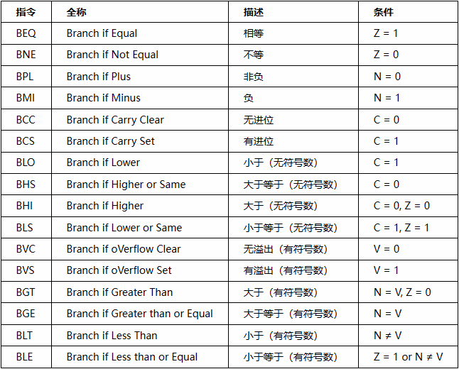
Compare Register Instructions
<span>CMP</span> Compare the values of two operands
CMP r1, #10   ; Compare the value of register r1 with the immediate value 10
BGT label     ; If the value of r1 is greater than 10, jump to label
<span>CMN</span> Compare the values of two operands’ complements
CMN r2, #5    ; Compare the complement of the value in register r2 with the immediate value 5
BLE label     ; If the complement of r2 is less than or equal to 5, jump to label
<span>TST</span> Perform a bitwise AND operation on two operands and set the condition codes based on the result.
TST r3, #0xFF ; Check if the low eight bits of register r3 are all 1
BEQ label     ; If the low eight bits of r3 are all 1, jump to label
<span>TEQ</span> Perform a bitwise XOR operation on two operands and set the condition codes based on the result.
TEQ r4, #0x80 ; Check the XOR result of the value in register r4 and the immediate value 0x80
BNE label     ; If the value in r4 is not zero after XORing with 0x80, jump to label
Compare Value Instructions
Stack Instruction Combination Suffixes
Four types of stacks:
This gives rise to 8 types of suffixes:
When understanding, we can break it down; for example, LDMIA can be understood as LDM IA in two parts. Here are some examples:
Read 4 words starting from address r0, storing them in registers r1-r4, then increment address r0 by 4.
LDMIA r0!, {r1-r4}
Increment address r0 by 4, then read 3 words starting from the new address, storing them in registers r1-r3.
LDMIB r0, {r1-r3}
Read 2 words starting from address r0, storing them in registers r1-r2, then decrement address r0 by 4, and store the last read word in lr register.
STMFD sp!, {r1-r3, lr}
Store the data in registers r1-r3 into the memory pointed to by address sp, then decrement sp by 16 (4 words), and store the data in lr register into the new address pointed to by sp.
LDMDB r0!, {r1-r2, lr}
Effect of the ‘!’ in Instructions
Generally, when the exclamation mark “!” appears after a register name, it indicates that the value of that register will be updated after executing the instruction. If there is no “!”, it indicates that the value of that register will not be updated before executing the instruction.
ldmia r0, {r2 - r3}
ldmia r0!, {r2 - r3}
Here, the effect of the exclamation mark is that the value of r0 changes during the ldm process, and the final value is written back to r0; the second ldm will change the value of r0, while the first one, without “!”, will not update the value of r0 after execution.
Effect of the ‘^’ in Instructions
The effect of ‘^’: When the target register contains pc, it will also write spsr into cpsr, generally used for returning from exception mode.
ldmfd sp!, {r0 - r6, pc}
ldmfd sp!, {r0 - r6, pc}^
Different Writing Styles in Assembly and Their Effects on Registers (Calculate Parentheses First)
Offset Method
LDR R0,[R1, #4]
Operation performed:
r0= *(r1 + 4)
Update in Advance
LDR R0,[R1, #4]!
Operation performed:
r0 = *(r1 + 4)
r1 = r1 +4
Update After:
LDR R0,[R1], #4
Operation performed:
r0=*r1, r1=r1+4

See You at Kanxue ID: Mr. Ermu
https://bbs.kanxue.com/user-home-979211.htm

# Previous Recommendations
1、Custom Linker Implementation Analysis
2、Reverse Analysis of VT-Enhanced Kernel Hooks
3、Aliyun CTF 2024 – Solution to ENOTYOURWORLD Problem
4、Hypervisor From Scratch – Basic Concepts and Configuration Testing Environment, Entering VMX Operation
5、V8 Vulnerability Exploitation Template for Object Forgery


Share It

Like It

Watching It