① Before checking the data bus system, ensure that all electronic control units (ECUs) connected to the data bus have no functional faults. Functional faults refer to those that do not directly affect the data bus system but will impact the functional process of a certain system. For example, if a sensor is damaged, the result is that the signal from the transmitter cannot be transmitted through the data bus. Such functional faults indirectly affect the data bus system and can hinder communication between ECUs that require that sensor signal. If functional faults exist, they should be addressed first. Note the faults and clear the fault codes from all ECUs.
② After eliminating all functional faults, if data transmission between ECUs is still abnormal, the data bus system needs to be checked.
When checking for faults in the data bus system, the following two possible situations must be distinguished:
■ Testing a two-wire data bus system consisting of 2 ECUs.
■ Testing a two-wire data bus system consisting of 3 or more ECUs.
③ If no cause for hardware damage can be found on the data bus, check if a specific ECU is causing the fault. Disconnect all ECUs that transmit data via the CAN bus, turn off the ignition switch, and connect one of the ECUs. For example, for Volkswagen system models, connect the diagnostic tool, turn on the ignition switch, and clear the fault codes from the newly connected ECU. Use function 06 to end the output, turn off and then turn on the ignition switch again, and after 10 seconds, use the diagnostic tool to read the contents of the fault memory of the newly connected ECU. If it shows “hardware damage,” replace the newly connected ECU; if it does not show “hardware damage,” connect the next ECU and repeat the process.
There may be records of CAN communication faults and CAN bus line faults in the CAN bus ECUs.
① CAN Communication Faults
Communication faults can occur in the following two scenarios:
■ Open circuit in the ECU.
■ Damaged ECU.
② CAN Bus Line Faults
There are several types of CAN bus line faults:
■ Short circuit in the CAN bus wire.
■ Open circuit in one of the CAN bus wires.
■ Grounding of the CAN bus wire.
■ Open circuit between CAN bus wires.
■ Cross connection between CAN-Low and CAN-High wires.
■ CAN-Low wire shorted to the positive terminal of the battery.
■ CAN-High wire shorted to the positive terminal of the battery.
■ CAN-Low wire shorted to the negative terminal of the battery.
■ CAN-High wire shorted to the negative terminal of the battery.
The reasons for communication faults in the CAN bus are as follows:
① Open circuit or short circuit in the CAN-Low or CAN-High communication lines.
② Damage to the connector, such as contact damage, dirt, or corrosion.
③ Voltage faults in the vehicle’s power supply system, such as those caused by a damaged ignition coil or grounding connections.
④ Fault in the communication component of a specific ECU.
⑤ Power supply fault of a specific ECU. When the battery is nearly depleted, the voltage may gradually drop, potentially leading to fault code storage, as not all ECUs shut down simultaneously due to voltage drop.
Short circuits to the positive terminal and grounding, as well as short circuits between wires, will not damage the ECUs, but in the most severe cases, it can cause the bus system to fail. The bus system in the vehicle can exhibit not only open or short circuit faults but also when moisture intrudes into the connectors in the bus system, it may create contact resistance between the ground, positive terminal, and CAN bus wires, causing abnormal operation of the bus system.
The CAN bus can be tested for voltage signals using a digital multimeter to roughly determine whether there is a fault in the signal transmission of the data bus. The testing methods are shown in the following diagram.
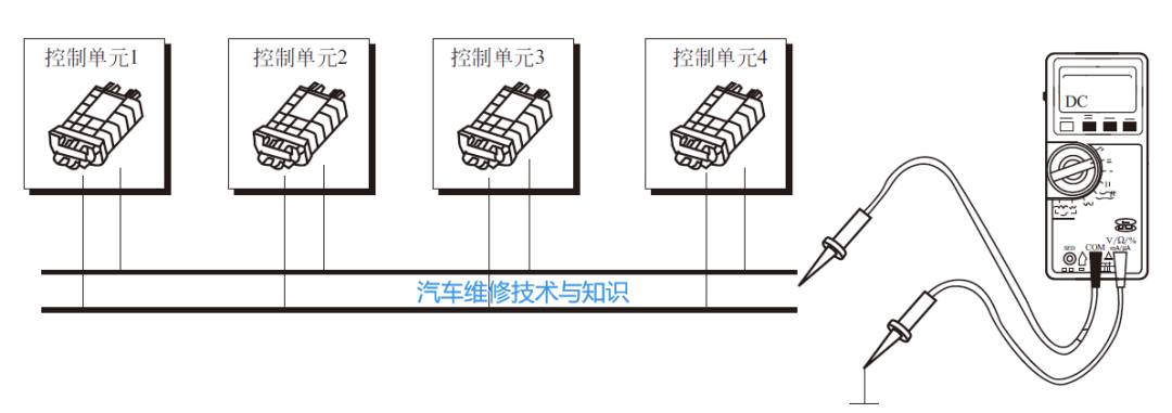
When measuring frequency signals with a digital multimeter, the multimeter has the characteristics of segmented sampling and effective value calculation, thus, the displayed value of the digital multimeter can only reflect the main signal voltage value of the measured signal and cannot display every detail of the measured signal. Therefore, when measuring the signal voltage of the CAN bus with a digital multimeter, the displayed value of the multimeter corresponds to the main signal voltage value of the CAN bus.
The voltage of the CAN-High signal is about 2.5V when the bus is idle, and when there is signal transmission on the bus, the voltage fluctuates between 2.5~3.5V. Therefore, the main voltage of CAN-High should be 2.5V, so the measurement value when using a multimeter should be 2.5~3.5V, which is greater than 2.5V but close to 2.5V.
Similarly, the voltage of the CAN-Low signal is about 2.5V when the bus is idle, and when there is signal transmission on the bus, the voltage fluctuates between 1.5~2.5V. Therefore, the main voltage of CAN-Low should be 2.5V, so the measurement value when using a multimeter should be 1.5~2.5V, which is less than 2.5V but close to 2.5V.
The signal of the comfort CAN bus is about 0 when the bus is idle, and when there is signal transmission on the bus, the voltage fluctuates between 0~5V. Therefore, the main voltage of CAN-High should be 0, so the measurement value when using a multimeter should be around 0.35V.
Similarly, the voltage of the CAN-Low signal is about 5V when the bus is idle, and when there is signal transmission on the bus, the voltage fluctuates between 0~5V. Therefore, the main voltage of CAN-Low should be 5V, so the measurement value when using a multimeter should be around 4.65V.
To measure the total resistance of the two termination resistors, the multimeter function of the VAS5051 diagnostic tool can be used, as shown in the figure below.
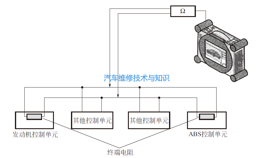
① Disconnect the wires (cables) from the positive and negative terminals of the battery.
② Wait for about 5 minutes until all capacitors are fully discharged.
③ Connect the VAS5051 diagnostic tool, invoke the multimeter function, connect the measuring leads, measure the total resistance of the termination resistors, and record the results.
④ Disconnect the connector of an ECU with a termination resistor (e.g., engine ECU) and observe whether the total resistance of the termination resistors changes.
⑤ Reconnect the connector of the first ECU (with a termination resistor, e.g., engine ECU) and then disconnect the connector of the second ECU (with a termination resistor, e.g., ABS ECU) and observe whether the total resistance of the termination resistors changes.
⑥ Analyze the measurement results.
The termination resistors set in the ECUs are not fixed resistance values; they are a combination of many measured resistors. For example, in a 1.9TDI model with a pump nozzle unit, the engine ECU is set to a 66Ω termination resistor. The termination resistor is designed according to the model, and the total resistance value depends on the vehicle’s bus structure.
After measuring the total resistance value, it is also necessary to disconnect the connector of an ECU with a termination resistor and perform two measurements of individual resistances. If the measured resistance changes after the ECU is removed, it indicates that both resistances are normal.
The termination resistors mounted on the driving CAN bus can be measured with a multimeter, but those mounted on the comfort CAN bus and information CAN bus cannot be measured with a multimeter.
For example, taking the Audi A2 1.4 model as an example, analyze the total resistance of its driving CAN bus. The two ECUs with termination resistors are connected through the CAN bus harness, and the two termination resistors are in parallel connection on the bus. The measured result is that each termination resistor has a resistance of about 120Ω, and the total resistance is about 60Ω. This measurement data allows us to conclude that the termination resistors of the driving CAN bus are normal.
It is important to note that the resistance value of a single termination resistor may not necessarily be around 120Ω; its specific value varies depending on the bus structure.
Similarly, analyze the individual resistance of the driving CAN bus in the Audi A2 1.4 model. After measuring the total resistance, disconnect the connector of an ECU with a termination resistor, and then perform the measurement. At this point, the displayed resistance on the screen should change (this measures the termination resistance of one ECU, and the actual measurement provides the individual termination resistance of the driving CAN bus).
If the resistance value does not change after disconnecting the connector of an ECU with a termination resistor, it indicates that there is a problem in the system. The termination resistor of the removed ECU may be damaged, or there may be an open circuit in the CAN bus. If the displayed resistance becomes infinite after the ECU is removed, then either the termination resistor of the ECU that was not removed is damaged, or there is an open circuit fault in the CAN bus wire leading to that ECU.