Do you remember the era when printers, mice, and modems came with those bulky connectors and thick cables? Literally, those that had to be screwed into your computer? These devices might be using the UART protocol to communicate with your computer. Although USB has almost completely replaced those old cables and connectors, UART is by no means outdated. You will find that many DIY electronic projects still use UART to connect GPS modules, Bluetooth modules, and RFID reader modules to Raspberry Pi, Arduino, or other microcontrollers.
UART stands for Universal Asynchronous Receiver/Transmitter. It is not a communication protocol like SPI and I2C, but rather a physical circuit or standalone IC within a microcontroller. The main purpose of UART is to send and receive serial data.
One of the best things about UART is that it only uses two wires to transmit data between devices. The principles of UART are easy to understand, but if you haven’t read the first part of this series, then the basics of the SPI communication protocol might be a good starting point.
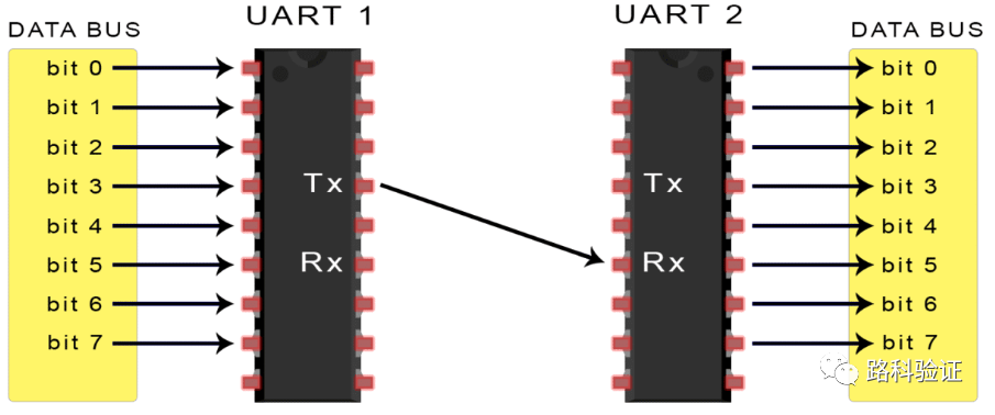
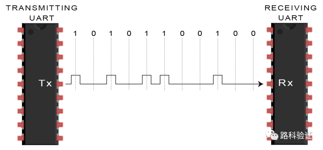
Introduction to UART CommunicationIn UART communication, two UARTs communicate directly with each other. The transmitting UART converts parallel data from a controlling device (such as a CPU) into serial form to send it serially to the receiving UART, which then converts the serial data back into parallel data for the receiving device.Only two wires are needed to transmit data between two UARTs. Data flows from the Tx pin of the transmitting UART to the Rx pin of the receiving UART: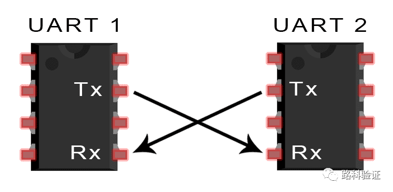 UART asynchronous data transmission means that there is no clock signal to synchronize the output bits of the transmitting UART with the sampled bits of the receiving UART. The transmitting UART replaces the clock signal by adding start and stop bits to the data packet being transmitted. These bits define the beginning and end of the data packet, allowing the receiving UART to know when to start reading these bits.When the receiving UART detects the start bit, it begins to read the input bits at a specific frequency called baud rate. Baud rate is a measure of data transmission speed, expressed in bits per second (bps). Both UARTs must operate at approximately the same baud rate. The baud rates of the transmitting and receiving UARTs can only differ by about 10% before the timing of the bits becomes too far apart.Additionally, both UARTs must be configured to send and receive the same data packet structure.
| Signal lines used | 2 |
| Maximum transmission speed | Up to 15200 baud, typically 9600 baud |
| Synchronization/Asynchronous | Asynchronous |
| Serial/Parallel | Serial |
| Maximum number of master devices | 1 |
| Maximum number of slave devices | 1 |
How does UART work?
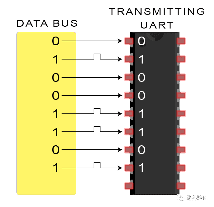
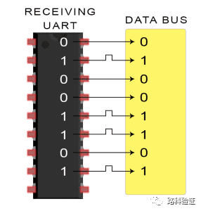
The UART that is going to send data receives data from the data bus. The data bus is used to send data to the UART from other devices (such as CPU, memory, or microcontroller). Data is transmitted in parallel from the data bus to the transmitting UART. After the transmitting UART retrieves the parallel data from the data bus, it adds the start bit, parity bit, and stop bit to create a data packet. The data packet is then serially output bit by bit on the Tx pin. The receiving UART reads the data packet bit by bit on its Rx pin. Then, the receiving UART converts the data back to parallel form and removes the start bit, parity bit, and stop bit. Finally, the receiving UART transmits the data packet in parallel to the data bus of the receiving end: 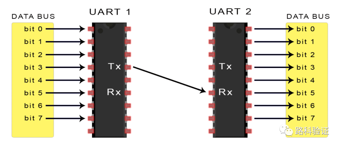
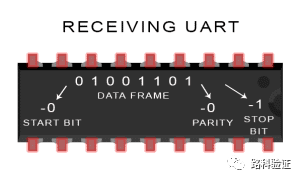
Data transmitted via UART is organized into packets, each packet contains 1 start bit, 5 to 9 data bits (depending on the UART), 1 optional parity bit, and 1 or 2 stop bits:
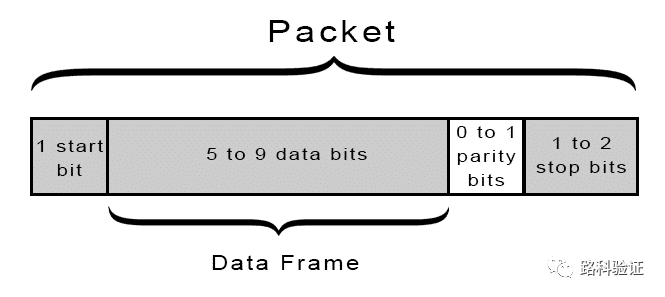
Start BitThe UART data transmission line typically remains at a high voltage level when not transmitting data. To begin data transmission, the transmitting UART pulls the transmission line from high to low voltage within one clock cycle. When the receiving UART detects the transition from high voltage to low voltage, it begins to read the bits in the data frame at the baud rate frequency.Data FrameThe data frame contains the actual data being transmitted. If a parity bit is used, the length of the data frame can be 5 bits, up to a maximum of 8 bits. If no parity bit is used, the length of the data frame can be 9 bits. In most cases, data is sent with the least significant bit first.Parity BitParity describes the property of a number, classified as even or odd. The parity bit is a way for the receiving UART to determine if any data has changed during transmission. Bits can change due to electromagnetic radiation, mismatched baud rates, or long-distance data transmission. After the receiving UART reads the data frame, it counts the number of bits that are 1 and checks whether the total is even or odd. If the parity bit is 0 (even parity), the number of 1 bits in the data frame should total to an even number. If the parity bit is 1 (odd parity), the number of 1 bits in the data frame should total to an odd number. When the parity bit matches the data, the UART knows that the transmission is error-free. However, if the parity bit is 0 and the total is odd; or if the parity bit is 1 and the total is even, the UART knows that the bits in the data frame have changed.Stop BitTo signal the end of the data packet, the transmitting UART drives the data transmission line from low voltage to high voltage for at least the duration of two bits.Steps of UART Transmission:
-
The transmitting UART receives data in parallel from the data bus:
-
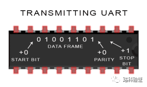
The transmitting UART adds the start bit, parity bit, and stop bit to the data frame:
-
The entire packet is serially sent from the transmitting UART to the receiving UART. The receiving UART samples the data line at the pre-configured baud rate:
-
The receiving UART discards the start bit, parity bit, and stop bit from the data frame:
-
The receiving UART converts the serial data back to parallel data and transmits it to the receiving end’s data bus:
 Advantages and Disadvantages of UARTNo communication protocol is perfect, but UART excels at its job. Here are some advantages and disadvantages to help you determine if they meet your project needs:Advantages
-
Only uses two transmission lines
-
No clock signal required
-
Includes parity bit for error checking
-
Can change its packet structure as long as both parties are set up for the packet structure
-
Well-documented and widely used method
Disadvantages
-
Maximum size of data frame is 9 bits
-
Does not support multiple slave systems or multiple master systems
-
Baud rates of each UART must be within 10% of each other
Continue reading the third part of this series, “Basics of I2C Communication Protocol,” to learn about another way electronic devices communicate. Or, if you haven’t read the first part, check out the basics of the SPI communication protocol.Series Review:Collection | SPI Communication Protocol in Electronic Communication Protocols
Reference original text:http://www.circuitbasics.com/basics-uart-communication/

Scan the QR code in the image above to go directly to the course page, and start a trial now
Previous Highlights:
Get the verification passphrase for the verification V2 course starting this Sunday
30w+ and giving away stocks and houses? 60+ IC companies’ salaries are rising across the board in 2019!
UVM RAL Model: Usage and Applications
We are preparing for the second offline training session, still serious and rigorous
If you suddenly get laid off, what is your Plan B?
[Rainbow Candy takes you into UVM]
Understand the changes from UVM-1.2 to IEEE1800.2, mastering these 3 points is enough