In the development of industry, fieldbus plays a very important role, mainly applied in fields such as petroleum, chemical, electric power, medicine, metallurgy, manufacturing, transportation, national defense, aerospace, agriculture, and buildings. Today, I will introduce several types of fieldbus such as the Modbus communication protocol, PROFIBUS, FF, and CAN bus.
Origin and Development of Modbus
Modbus was invented by Modicon (now a brand of Schneider Electric) in 1979 and is the world’s first true bus protocol used in industrial sites.
To better popularize and promote Modbus in Ethernet-based distributed applications, Schneider has transferred the ownership of the Modbus protocol to the IDA (Interface for Distributed Automation) organization and established the Modbus-IDA organization, laying the foundation for the future development of Modbus. In China, Modbus has become the national standard GB/T19582-2008. According to incomplete statistics, as of 2007, the number of Modbus node installations has exceeded 10 million.
To better popularize and promote Modbus in Ethernet-based distributed applications, Schneider has transferred the ownership of the Modbus protocol to the IDA (Interface for Distributed Automation) organization and established the Modbus-IDA organization, laying the foundation for the future development of Modbus. In China, Modbus has become the national standard GB/T19582-2008. According to incomplete statistics, as of 2007, the number of Modbus node installations has exceeded 10 million.
A general language used on electronic controllers. Through this protocol, controllers can communicate with each other, and between controllers and other devices via a network (such as Ethernet).
When communicating on the same Modbus network, this protocol determines that each controller needs to know its device address, recognize messages sent by address, and decide what action to take.
This protocol supports traditional RS-232, RS-422, RS-485, and Ethernet devices. Many industrial devices, including PLCs, DCS, smart instruments, etc., are in use.
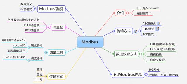
Standard, open, users can use the Modbus protocol freely and confidently without paying licensing fees or infringing intellectual property rights. Currently, there are more than 400 manufacturers supporting Modbus, with over 600 types of products supporting Modbus.
Modbus can support multiple electrical interfaces, such as RS-232, RS-485, etc., and can transmit over various media, such as twisted pair, fiber optics, and wireless.
The frame format of Modbus is simple, compact, and easy to understand. It is user-friendly, and vendors find it easy to develop.
What is FF Fieldbus?
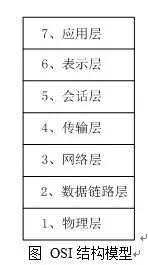
The Foundation Fieldbus, abbreviated as FF, is based on the ISO/OSI open systems interconnection model, taking its physical layer, data link layer, and application layer as the corresponding levels of the FF communication model, and adding a user layer on top of the application layer.
Foundation Fieldbus has two communication rates: low-speed H1 and high-speed H2. H1 has a transmission rate of 3125 Kbps, with a communication distance of up to 1900m (can be extended with repeaters), supports bus power supply, and supports intrinsically safe explosion-proof environments. H2 has transmission rates of 1 Mbps and 2.5 Mbps, with communication distances of 750m and 500m.
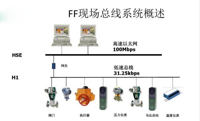
The physical transmission medium can support twisted pair, fiber optics, and wireless transmission, with the protocol complying with IEC1158-2 standards. The transmission signal of the physical medium uses Manchester encoding, where the central position of each transmitted data bit either has a positive or negative transition. A positive transition represents 0, while a negative transition represents 1, thereby providing sufficient positioning information in the serial data stream to maintain time synchronization between the sender and receiver. The receiver can determine the “1” or “0” state based on the polarity of the transition and can accurately locate based on the center position of the data.
Origin of PROFIBUS
PROFIBUS stands for Process Field Bus. It is a national industrial fieldbus protocol standard established in Germany in the early 1990s, designated DIN19245, completed by thirteen industrial enterprises and five research institutes over a period of more than two years.
In 1996, it was approved by the European Committee for Electrotechnical Standardization as a European standard EN50170. According to European standardization rules, EN50170 was automatically recognized by all national standardization organizations in Europe that year. Germany canceled the original national standard DIN19245 for PROFIBUS and replaced it with EN50170.
From now on, all public tenders in Europe are based on EN50170. EN50170 provides the highest standard for manufacturers and users in protecting investments. PROFIBUS provides a transparent network from sensors to management levels. Because of this, PROFIBUS can be applied in many areas—from the automotive industry, machinery manufacturing, food industry, transportation to environmental engineering.
The maximum transmission information length is 255B, the maximum data length is 244B, and the typical length is 120B.
The network topology can be linear, tree, or bus type, with active bus termination resistors at both ends.
The transmission rate depends on the network topology and bus length, ranging from 9.6Kb/s to 12Mb/s.
The number of sites depends on signal characteristics, such as for shielded twisted pairs, each segment can have 32 sites (without repeaters), and a maximum of 127 sites with repeaters.
The transmission medium can be shielded/unshielded twisted pairs or fiber optics.
When using twisted pairs, the maximum transmission distance can reach 9.6km, while the maximum transmission length with fiber optics is 90km.
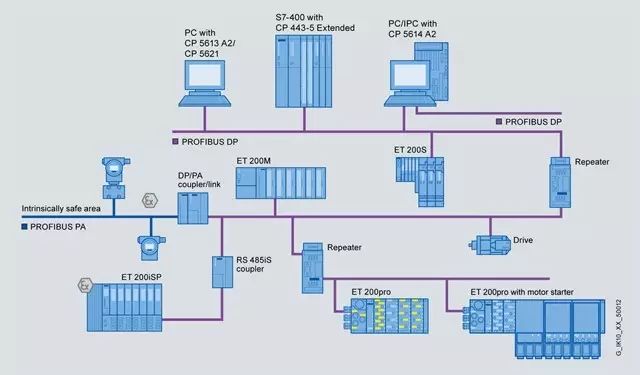
The transmission technology includes DP and FMS RS-485 transmission, PA IEC1158-2 transmission, and fiber optic transmission.
A single bus-oriented protocol is adopted, including token passing between master stations and a master-slave mode between slave stations.
Data transmission services include both cyclic and non-cyclic types.
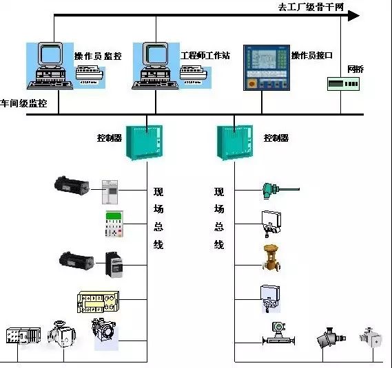
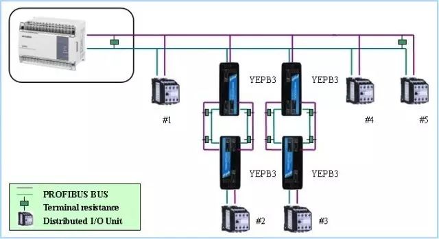
Field Device Layer
The main function is to connect field devices such as distributed I/O, sensors, actuators, and lighting control devices, achieving field device control and inter-device interlocking control. The master station is responsible for bus communication management and communication with all slave stations.
Workshop Monitoring Layer
For example, the connection between the main controllers of three production lines in a workshop completes workshop-level equipment monitoring. Workshop-level monitoring includes online monitoring of production equipment status, equipment failure alarms, and maintenance. It usually also has workshop-level production management functions such as production statistics and production scheduling. Workshop-level monitoring typically requires a monitoring room, with operator workstations and printing devices. The workshop-level monitoring network can use Profibus-FMS, which is a multi-master network where data transmission speed is not the most important, but the ability to transmit large volumes of information.
Factory Management Layer
Operator workstations in the workshop can connect to the workshop management network via hubs, sending workshop production data to the factory management layer. The workshop management network acts as a subnet of the main network, connecting to the factory backbone network through switches, bridges, or routers, integrating workshop data into the factory management layer.
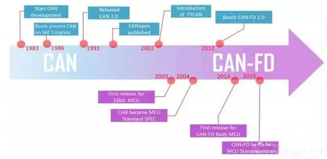
Origin of the CAN Bus
The CAN bus was developed by BOSCH in Germany and several semiconductor manufacturers, initially designed specifically for the automotive industry for data communication between internal measuring and actuating components. It has now been promoted for use in discrete fields and has been approved as an international standard IS011898 (communication rate 1 Mbps) and IS011519 (communication rate 125 Kbps) by the ISO/TC22 technical committee.
The communication medium used is twisted pair, with a maximum communication rate of 1 Mbps/40m, and a maximum direct transmission distance of 10km/50kbps. The maximum number of devices that can be connected is 110.
The signal transmission of CAN uses a short frame structure, with a maximum of 8 valid bytes per frame, resulting in short transmission times and low probability of interference.
CAN supports multi-master operation mode. Any node on the network can actively send information to other nodes at any time, supporting point-to-point, one-to-many, and global broadcast methods for receiving/sending data. It uses bus arbitration technology, allowing nodes with higher priority to continue sending data while nodes with lower priority stop sending to avoid bus conflicts.
In the field of industrial control, the CAN bus is mainly used for low-speed fault-tolerant CAN according to the ISO11898-3 standard, while in the automotive field, high-speed CAN is commonly used at 500 Kbps.
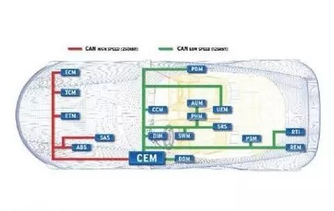
A certain imported model has multiple control networks for body, comfort, multimedia, etc., where the body control uses CAN network, comfort uses LIN network, and multimedia uses MOST network. The CAN network is the main network, controlling engine, transmission, ABS, and other safety modules, sharing RPM, vehicle speed, oil temperature, etc., to achieve intelligent control of the car, such as automatically locking doors at high speeds, and automatically opening doors when airbags deploy.
CAN systems are also divided into high-speed and low-speed, with high-speed CAN systems using hard wiring for power, at a speed of 500 Kbps, controlling ECU, ABS, etc.; low-speed CAN is comfort-oriented, at a speed of 125 Kbps, mainly controlling instruments and anti-theft systems.
——-End——-
Source: Internet
Link: How can electrical engineers transition to the industrial robotics field?
Click: The promotion path from 3K to 15K monthly income (share with someone who needs it)
We are not just carriers of valuable content

Distance from Industrial Robot Experts is Just a Follow Away
Guidance Robot Academy, a cradle for robotic engineers