
Casting Technology for Integral Turbine Runners Based on 3D Printing Technology
Ma Bin, Li Yongxin, Li Wending, Li Kun, Li Caihong
(Shared Steel Casting Co., Ltd., Yinchuan, Ningxia 750021)
Abstract: The integral turbine runner products have high working loads and stress, requiring strict internal quality of the castings. Due to the complex structure and limited operational space, the forming of the runner is difficult, and controlling dimensions is challenging. Additionally, the product has many thermal nodes and difficulties in shrinkage compensation, which can lead to turbulence and difficulty in slag floating during the casting process. To address these challenges, a set of integral casting technology using 3D printed sand cores has been developed. Through reasonable design of the riser and pouring system, advanced MAGMA simulation software was used to analyze and optimize the casting process of the runner, solving the problems of shrinkage compensation and slag inclusion during casting. The precise forming through 3D printing ensures the dimensional accuracy of the runner. Actual inspection results of the castings indicate that all indicators meet the requirements.
Keywords: Turbine runner; Casting process; 3D printing; Numerical simulation
The turbine runner converts the pressure energy and potential energy of water into rotational mechanical energy of the runner, which is transmitted to the generator shaft through the turbine main shaft[1-7]. With the increasing precision requirements for runners in hydropower stations, more and more turbine runners are produced using integral casting methods. The structure of the turbine runner mainly consists of the upper crown, blades, and lower ring, which can be divided into integral cast runners and welded runners based on structural form. An integral cast runner refers to the upper crown, blades, and lower ring being cast as a single piece, forming a single runner casting[7-13]. With the application of 3D printing technology, the runner flow channel sand cores are printed using 3D printers, followed by integral casting to form the runner casting. Using 3D printed sand molds for integral casting is cost-effective, has a short manufacturing cycle, and provides high precision in the appearance quality of the castings, significantly reducing the cycle and cost of subsequent welding[4-18]. The runner must withstand enormous alternating loads during operation, impacted by high-pressure water heads and sediment, making the quality of the castings highly demanding. This paper studies how to produce integral cast runners using 3D printed sand cores to achieve castings free of shrinkage cavities, shrinkage porosity, and internal quality that meets quality grade requirements.
1 Product Introduction
The runner profile dimensions are φ2242mm×1205mm, weight 5701kg, maximum wall thickness 170mm, minimum wall thickness 40mm, and material is GX4CrNi13-4. Its structure is shown in Figure 1.
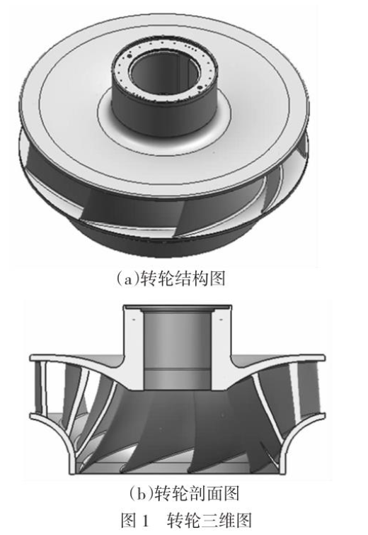
Due to its unique structural characteristics, the structure of the pump turbine must control the stress on the runner blades and improve their fatigue resistance after meeting the hydraulic design conditions. The overall requirements for the mixed-flow pump turbine runner are high, and the complex processes and forming require ensuring that the dimensions of the flow surface during casting meet the requirements, with no defects such as porosity, sand inclusion, shrinkage, or cracks. Therefore, it is necessary to study the casting process and forming scheme to solve the casting issues of the impeller[9-26].
2 Casting Process Design
2.1 Determining the Casting Scheme
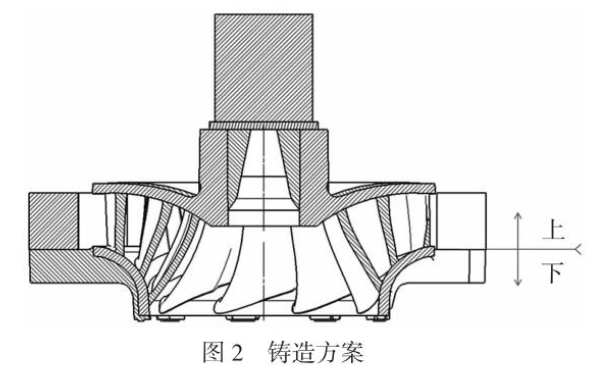
Based on the structural characteristics of the casting, considering the design of the riser and filling, the casting scheme with the upper crown facing up was determined, as shown in Figure 2.
2.2 Simulation Analysis of Thermal Nodes in the Casting
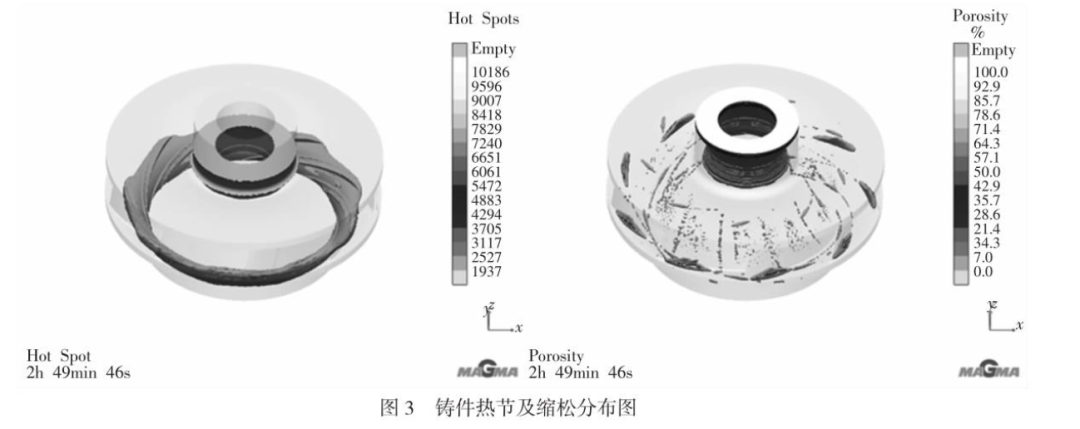
According to the above casting scheme, combined with the simulation of MAGMA software, the distribution and morphology of thermal nodes in the casting were determined, as shown in Figure 3. The simulation results show that the thermal nodes in the casting are mainly concentrated at the junctions of the lower ring and blades, the upper crown and blades, and the upper crown main shaft. Due to the elongated curved shape of the flow channel in the integral cast runner, the thermal node morphology at the junctions of the blades with the upper crown and lower ring is mainly in a spiral band shape, which has a long distribution distance and is not easy to directly compensate for shrinkage. The traditional approach is to design small risers dispersedly, which has the disadvantages of low yield and a large amount of finishing work later.
2.3 Riser Design
The riser is designed using the modulus calculation method. The modulus refers to the ratio of the volume of the solidified body to the surface area of the heat dissipation. Generally, the modulus at the thermal node of the casting is calculated first, followed by the modulus of the riser, with the modulus relationship being:
Mriser=1.2~1.4Mcasting(for open risers take 1.2, for blind risers take 1.4).
The upper crown uses a single riser for shrinkage compensation; the riser is located at the end face of the upper crown main shaft, with the inner side of the main shaft starting from the lower plane of the riser, set from top to bottom with a thick-to-thin gradient for solidification compensation.
(1) Compensation for the upper crown and the junction with the blades. Based on the thermal node distribution of the casting, the position of the upper crown main shaft end face is the maximum thermal node area, which is convenient for placing and removing the riser, so it is chosen to set the riser here; the main shaft is a uniform wall structure. To help the main shaft smoothly compensate from top to bottom, a compensation pad is set on the inner side of the main shaft. At the same time, to ensure that the thermal node at the junction of the upper crown and blades is compensated, the usual method of setting the riser at this position is changed to a method of leading the compensation pad from the root of the main shaft to the outer circle of the upper crown. The compensation pad starts from the main shaft to the outer circle of the upper crown, transitioning from thick to thin, with a solidification shrinkage gradient of 8%~12%. The compensation pad extends as a complete circle along the upper surface of the upper crown, radiating outward from the root of the main shaft, and its thickness should not be too thick, which can ultimately be removed by machining, avoiding the complex operation of individually cutting and removing the risers.
(2) Compensation for the lower ring and the junction with the blades. According to the thermal node profile of the casting, there will be three junctions at the same section (or called longitudinal shrinkage direction) between the lower ring and blades, forming independent thermal nodes that cannot effectively compensate for the thermal nodes themselves, ultimately leading to shrinkage porosity. To ensure that the thermal nodes at the junction of the lower ring and blades are sufficiently compensated, a long longitudinal riser neck and compensation pad are set, with the upper end face of the riser neck designed as a riser to compensate for the thermal nodes of the entire lower ring and the junction with the blades. The compensation pad forms a longitudinal shrinkage gradient from top to bottom, with a solidification shrinkage gradient meeting a 10%~15% increment ratio. This compensation pad is set according to the distribution of the blade rotation direction, with each blade corresponding to a compensation pad and riser. The specific process is shown in Figure 4.
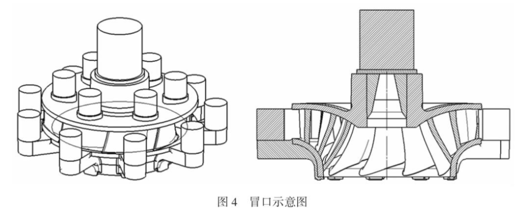
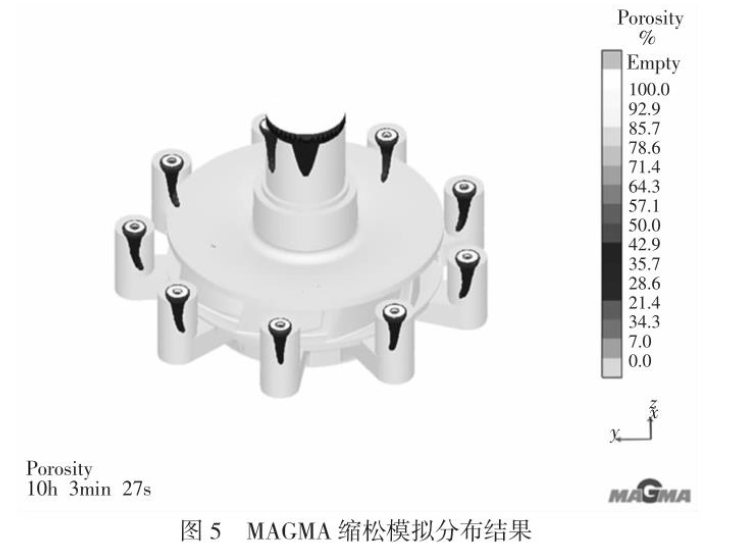
By forming a channel for shrinkage compensation during the solidification period through the metal compensation and the body of the casting, it ensures that the un-solidified molten steel in the riser area can continuously supplement the previously solidified casting body area, with the riser set at the last solidification area, concentrating the last solidification part of the casting in the riser area, leading shrinkage and shrinkage porosity to the riser area, ensuring the formation of a dense casting body, preventing shrinkage in the runner body. Verification through MAGMA solidification simulation shows that this process scheme has no excessive defects, with simulation results shown in Figure 5.
2.4 Pouring System Design
The pouring system must ensure that the molten steel enters the mold cavity smoothly, quickly, and continuously, and can successfully vent and float slag while regulating the temperature distribution within the cavity, enhancing the casting’s shrinkage compensation[2].
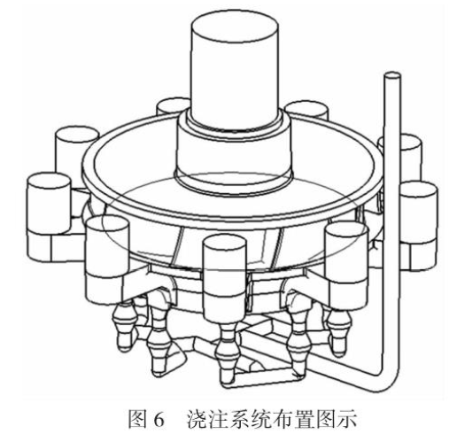
To avoid secondary oxidation of the molten steel during pouring and reduce sand washing during the filling process, a rapid and stable multi-point inflow pouring principle for the runner casting was established. The pouring system adopts an open pouring method with a single ladle and single pouring gate. The molten steel enters the primary horizontal pouring channel from the direct pouring channel, and after multi-stage diversion through the horizontal pouring channel, it enters the casting cavity through the inner pouring gates set below each compensation pad. Before this, filters are set below each inner pouring gate to prevent inclusions and secondary oxidation slag from entering the casting, while reducing the flow rate of the molten steel to prevent erosion of the mold walls. The design of the pouring system is shown in Figure 6.
3 Forming Scheme Design
Due to the flow surface of the runner’s inner cavity being formed by the curved surfaces of multiple blades, this process integrates the advantages of both 3D printing and wooden mold samples, using 3D printing for the inner core and real samples for the outer mold, combining the two methods.
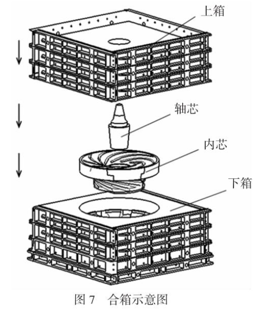
The outer mold is a simple shape of a rotating body, made using CNC machines to produce wooden molds, meeting the dimensional accuracy of the outer mold and the mass production of products. By using resin-bonded sand molding to fill the sand, high-refractory ceramic tubes are used to lay out the pouring system, reducing surface defects caused by erosion. After the hardening of the mold sand, box opening, and other sand mold making processes, the lower ring cavity and upper crown profile of the integral cast runner are formed. The inner core and shaft core of the integral cast runner are printed using 3D printing. Among them, the inner core can be printed in one piece or appropriately segmented and printed separately for assembly, with the printed sand core having a dimensional accuracy of ±1mm, greatly improving the sand core precision of the integral cast runner, facilitating near-net shape formation. Finally, the inner core, shaft core, and upper box (upper crown profile) are assembled with the lower box (lower ring cavity) to ultimately form the cavity of the integral cast runner, refining the molten steel, pouring, cooling, and after removing the riser and heat treatment, the integral cast runner is formed. The assembly diagram is shown in Figure 7.
4 Production Verification
Verification of the actual produced castings shows that in terms of dimensions: the dimensions of the casting flow channels are all within tolerance, and the overall dimensions are good, as shown in Figure 8. In terms of non-destructive testing: the upper crown, lower ring, and blade flow channels of the runner have no surface sand sticking or excessive defects, indicating that the casting solidification compensation scheme and forming scheme are reasonable, achieving product development.

5 Conclusion
This paper analyzes the difficulties of the integral casting process and forming scheme for turbine runners, optimizing the casting process through the analysis and simulation of banded thermal nodes using MAGMA computer simulation technology, solving casting issues; the use of 3D printing solutions addresses the forming issues of the castings.
Verification of the actual produced castings shows: the interior of the runner is basically free of sand sticking; non-destructive testing shows no excessive defects; the overall dimensions of the castings are good, all within tolerance. The verification results indicate that this process scheme and the 3D printing forming scheme are effective and can produce qualified integral turbine runners.
References:
[1] Li Wenqing. Application of Cavitation Monitoring Technology for Turbine Runners in Hydropower Units [J]. Zhejiang Electric Power, 2005(04):76-78.
[2] Li Shihua, Wang Shengli, Wan Yuan, et al. Research and Engineering Practice on the Detection Method of Collision and Grinding in the Runner Chamber of Bulb Turbine Hydropower Units [J]. Jiangxi Electric Power, 2019, 43(10):47-50.
[3] Zhang Leike, Zhang Jinjian, Wang Xuenie, et al. Analysis of Coupled Vibration Characteristics of Rotor-Runners in Hydropower Units [J]. Journal of Hydropower Generation, 2021, 40(09):102-112.
[4] Zhang Junbao, Yang Xiaobing, Lü Youqing, et al. Research on the Process of Semi-Integral Cast Runners [J]. Large Castings and Forgings, 2022(03):20-22.
[5] Li Shuming, Yang Ye, Wan Yuan, et al. Diagnosis and Analysis of Abnormal Vibrations in the Runner Chamber of Large Horizontal Hydropower Units [J]. Jiangxi Electric Power, 2020, 44(04):58-60+66.
[6] Xie Junhu, Lin Shaobin. Overlay Welding of Stainless Steel Layers in Large Hydropower Runners [J]. Large Castings and Forgings, 2020(06):21-23.
[7] Huang Jianming, Ma Youping. Integral Casting Process of Impact Turbine Runners [J]. Casting, 2002(01):49-51.
[8] Zhu Bangcai, Yang Shuo, Yang Hong. Marking and Measurement Methods for Integral Mixed-Flow Runners [J]. Large Electric Machine Technology, 1996(04):58-61+65.
[9] Zheng Jianfeng, Ye Fuxin. Analysis and Treatment of Causes for the Falling Off of the Leakage Ring in Mixed-Flow Hydropower Unit Runners [J]. Zhejiang Electric Power, 2010, 29(01):38-40.
[10] Zhang Chuan, Han Tongtong, Zhang Junbao, et al. Development of Casting for Large Hydropower Runners [J]. Large Castings and Forgings, 2022(03):17-19+22.
[11] Zhang Lei, Wu Yin, Li Ting. Quality Control Methods for Integral Casting Mixed-Flow Runners [J]. China Foundry Equipment and Technology, 2021, 56(03):57-60.
[12] Zhao Shuwen. Detection Methods for the Dimensions and Appearance of Integral Cast Runners [J]. China Foundry Equipment and Technology, 2021, 56(03):73-77.
[13] Zhang Yongming, Wang Dong. Assembly and Welding Technology for Hydropower Runner Chambers [J]. Metal Processing (Thermal Processing), 2012(06):47-50.
[14] Xu Jianping, Bai Changyou, Yang Jining. Improvement of Processing Technology for Integral Mixed-Flow Turbine Runners [J]. Mechanical Research and Application, 2019, 32(06):189-190+193.
[15] The First Installed Hydropower Project in Tibet with a Capacity of Over One Million Kilowatts, the First Runner of the Suwalong Hydropower Station Completed by Dongfang Electric Manufacturing [J]. Dongfang Electric Review, 2020, 34(03):63.
[16] Shenyang Foundry Research Institute Co., Ltd. Research and Application of 3D Printed Sand Core Technology for Integral Mixed-Flow Runners: Proceedings of the Casting Branch of the Chinese Mechanical Engineering Society [C]. Wuhan, 2019.
[17] Feng Huiqi, Huo Jinping. Summary of CNC Processing Technology for Integral Cast Runners [J]. Science and Technology Innovation and Application, 2014(09):62.
[18] Cheng Yue. Preventive Measures for Cracking of Turbine Runners in Hydropower Equipment [J]. Electrical Engineering Digest, 2010(06):32-33.
[19] Huang Jianming, Jie Yinhui, Ma Youping, et al. Causes and Prevention of Porosity and Cold Seals in Stainless Steel Integral Runners [J]. Casting Technology, 2002(01):43-45.
[20] Li Fengyu, Xu Weihong. Research on the Casting Process of Integral Cast Runners at Lishimen Hydropower Station [J]. Large Electric Machine Technology, 2002(04):38-40.
[22] The World’s First One Million Kilowatt Hydropower Unit Runner Begins Welding [J]. Sichuan Hydropower, 2018, 37(01):133.
[24] Zhang Yongming, Wang Dong. Assembly and Welding Technology for Hydropower Runner Chambers [J]. Metal Processing (Thermal Processing), 2012(06):4750.
[26] Cheng Yue. Preventive Measures for Cracking of Turbine Runners in Hydropower Equipment [J]. Electrical Engineering Digest, 2010(06):32-33.
Published in:China Foundry Equipment and Technology.2024.05.40-44.