Make a Mini Quadcopter with Open Source Flight Control Kit

Quadcopters are no longer a novelty; many troubled areas around the world use quadcopters for reconnaissance. With just a few thousand yuan, you can buy a set of “White House-style” quadcopters. However, making a Mini quadcopter that is smaller than your palm and weighs just over 30 grams would definitely be more fulfilling.
This tutorial will teach you how to make a Mini quadcopter using an open-source flight control system based on the Arduino platform (Flight Control System, abbreviated as “FC”).
Materials Required:
MWC Flight Control (PCB designed in the shape of a quadcopter) *1
716 or 720 hollow cup motor *4
45mm propellers with a hole diameter of 0.75mm *4 (2 clockwise and 2 counterclockwise, total of 4)
300mAh 25C 3.7V lithium battery *1
USB to TTL downloader *1
HC-06 Bluetooth module *1
Several 2.54mm Dupont wires
Optional:
AR6100e DSM2 micro receiver *1
RC remote control: Walkera Devo 7e or Devo 10 (can be flashed with open-source Deviation firmware, compatible with various systems, extremely powerful)
Tools:
30-50W soldering iron
Hot glue or 20mm wide 3M double-sided tape
Step 1: Understand the Principles of Quadcopters


The control principle of quadcopters/multi-rotor vehicles is not complex. Taking the quadcopter as an example, the four rotors create a quad-rotor plane, controlled by the flight control system to adjust the output of each motor, thereby controlling the tilt of the entire quad-rotor plane and changing the flight direction through lift force. We all know that the rotation of propellers generates counter-torque on the body, hence the four propellers of the quadcopter are arranged such that adjacent pairs rotate in opposite directions, while the two pairs rotate in the same direction, to counteract the overall counter-torque and maintain stability. To rotate in a horizontal direction, simply accelerate the two propellers rotating in the same direction while decelerating the other two, breaking the balance of counter-torque while keeping the total lift unchanged, allowing for a gradual turn.
The flight control is the core of multi-rotor vehicles. The most basic flight control consists of a 3-axis gyroscope that senses the displacement changes of the vehicle along the X, Y, and Z axes, controlling each motor to compensate for power to maintain the balance of the entire vehicle.
MWC stands for MultiWii Flight Controller, initially started as an open-source project by the author using sensors from the Wii motion controller (or Nunchuk) combined with an Arduino Pro Mini. As more people supported and contributed code, its performance improved, and some businesses gradually commercialized it, like the Mini WMC flight controller manufactured by “Yangtze Smart Technology” that we are using this time. Its MCU is an Atmel 328P, the same as mainstream Arduinos, with the sensor chip being an MPU6050 3-axis gyroscope + 3-axis accelerometer. Additionally, the board has a power management chip and MOSFETs to drive hollow cup motors, which makes it easy and quick to assemble a Mini quadcopter.
Step 2: Solder the TTL Serial Downloader, Battery, Receiver, and Other Interfaces


Find a 2.54mm pin header in the material package. These pins are for various interfaces on the flight control. You can see that the front end of the flight control (the direction marked with ▲ is the front) has 5 holes, which are the TTL serial positions, labeled GND, 5V, TX, RX, and DTR. Break off a segment of 5 pins from a pin header and insert the shorter end into the 5 holes. Don’t worry, it will fit; this is a standard 2.54mm (1/10 inch). Now flip it over and solder the exposed short pins to the pads on the bottom of the flight control, thus preparing the TTL interface. This can connect to the USB-TTL downloader and Bluetooth module, etc.
Using the same method, you need to break off a 6-pin header to solder a receiver interface, labeled GND, VCC, YAW, THRO, PITCH, and ROLL, which means ground, power supply, and direction, throttle, pitch, and roll channels (are you dizzy? More on that later).
At the rear end of the flight control, there are two holes for the power supply’s +/- terminals. Similarly, break off a 2-pin header and solder it into the holes to connect a small battery, providing power to the entire quadcopter.
Step 3: Install the Hollow Cup Motors


This is another soldering job. If your soldering skills are not up to par, you might want to consider getting a soldering certificate: P (I will later introduce some electronic soldering tips in my logs, stay tuned).
After receiving the Mini flight control board, you will see four round holes at the ends of the four “legs”; this is where the hollow cup motors are installed. Insert the small motor into the round hole with the motor shaft facing up. The inner circle of the hole has a ring of metal pads on the PCB. Here, you can use a soldering iron to tin and fix the metal casing of the small motor to the pad. Note that when securing the motor, keep it perpendicular to the flight control board, ensuring that the positions of the four motors are consistent and that they are all at the same height.
After securing the four motors, flip the board over to see the solder pads for the motor’s positive and negative terminals, labeled VCC and GND. We can solder the positive and negative leads of each motor to the VCC and GND pads. Generally, the red wire is positive, connected to VCC, while the blue or black wire is negative, connected to GND. Later, we might find that the motor direction is incorrect, and we may need to resolder. But for now, let’s not worry; if it doesn’t solder, it won’t spin.
Find your four small propellers; note that they come in pairs with two clockwise and two counterclockwise. Install them according to the layout shown in the diagram, considering their rotation direction.
Small tip: Each blade of the propeller has a curved surface, and the convex side should face up (or forward). The side that is raised is the direction of rotation, which will help you determine how to install each propeller on the quadcopter.
Step 4: Prepare Your Arduino IDE


Now, your Mini quadcopter is 75% complete and needs to be connected to a computer to download the flight control source code.
You need to find a PC or Mac that has Arduino IDE installed and be ready. Download and extract the file, placing the “MultiWii” folder into the Arduino IDE’s “libraries”. Where is the Arduino IDE’s library? You can check Arduino’s “File – Preferences”. If you don’t understand this, it means you are not familiar with Arduino yet, so ask Baidu or wait for me to slowly explain it: P After copying, reopen the Arduino IDE, and you will see the “MultiWii” project in the “File – Libraries” menu. Click it, and a new Arduino IDE window will open with many tabs; this is the source code for the MWC flight control project.
Download: MultiWii Firmware V2.2 Arduino Official Homepage
Step 5: Download the MWC Flight Control Source Code


Take out your USB-TTL downloader; one end has a Mini USB connector to connect to your computer’s USB cable. This device usually automatically finds the driver when connected to the internet. If it doesn’t, download and install the driver here. The other end has five or six pins that you need to connect to your flight control’s TTL interface using Dupont wires. Connect VCC to the flight control’s 5V, GND to GND, TX to RX, RX to TX, and DTR to DTR, and you’re all set.
Insert the battery into the quadcopter, turn on the switch (there are two switches on the flight control, one for charging and one for power; both should be turned on), connect the TTL downloader to the computer USB, and open the MultiWii project in the Arduino IDE. In the “Tools – Board” menu, select “Arduino Pro Mini (5V, 16Mhz)” and select the correct COM port, then you can prepare to download.
Before downloading, you can verify it first, by clicking the checkmark on the left side of the Arduino IDE toolbar. If verification fails, congratulations, you may need the Arduino IDE version 1.0x, as the MWC flight control project is an older project from before 2013 that uses older library files. If your Arduino IDE is too new, it might cause issues. Go to the Arduino official website to download version 1.0x.
If verification is successful, click the right arrow button on the Arduino IDE to start downloading. During the download, the TTL downloader will flash quickly, and a progress bar will appear. When the download is finished, the blue indicator light on the flight control will blink once. Download: USB-TTL downloader driver
Step 6: Detect the Quadrotor in MultiWiiConf Software

Now, I must tell you that I have dug a pit for you. If you only spent 200 yuan on the kit, and it only includes the USB-TTL downloader and Bluetooth module, you may need to spend a few hundred more to fill the pit. There is a saying: “Building RC models is like the deep sea; from now on, integrity is a passerby.” During this debugging step, you may find that you indeed need an RC remote control and receiver, as you may see many switch settings, channel travel settings, etc., especially since quadcopters generally have lock and unlock settings to ensure safety after powering on. It can be a bit troublesome without a remote control. Okay, I will later provide a detailed guide on selecting and setting up a remote control (there’s another saying: “Bringing people into the model, worth seven levels of pagoda”. Amitabha, another pit).
Download the MultiWiiConf software here; it’s a portable software that doesn’t require installation. However, if it doesn’t respond when you double-click it, that’s normal because your computer doesn’t have the Java environment. Download and install the Java environment here, and you will be able to run it normally.
Use the USB to TTL downloader to connect the Mini quadcopter to your computer’s USB port, and open the MultiWiiConf software on the computer. You will see a COM port appear under PORT COM, which is your USB to TTL downloader’s COM port. Click it, and after a moment, it will connect successfully. The blue LED will flash rapidly and then turn off, indicating that initialization is complete.
The upper part of the software is the PID setting window for the flight control. Click READ to read the PID parameters of the flight control. In the lower part of the software is the sensor attitude detection window. Click START to read data, and you will see the output status of all sensors.
Before flying, you need to observe and adjust necessary options, mainly including the following aspects: set channel directions, calibrate channel neutral points, and check if the sensor output signals are correct (if not, it indicates a fault in the flight control); test if the flight control operates normally after starting the motors. So, a remote control is essential here. Download: WMC Flight Control PC Setting Tool MultiWiiConf JAVA Environment
Step 7: Remote Control Settings and Unlocking


If your kit includes a receiver and a remote control, you need to connect the receiver to the control input port of the quadcopter. Do you remember the GND, VCC, YAW, THRO, PITCH, and ROLL pins on the quadcopter? Your receiver will also have these channels: THRO represents the throttle channel, ROLL or AILE represents the roll (aileron) channel, PITCH or ELEV represents the pitch (elevator) channel, and YAW or RUDD represents the direction channel. Find the signal wires for these channels, usually marked with a small long wall-like pin, and connect them to the YAW, THRO, PITCH, and ROLL pins on the flight control. Connect the VCC and GND of the flight control to any channel of the receiver’s +/- terminals, as all channels’ positive and negative terminals are in parallel. Now, when you turn on the quadcopter’s power, the receiver’s light will illuminate. If your receiver has never been used before, you will also need to bind it with the remote control (Banding), usually by inserting the binding wire into the specified channel and turning on the remote control to complete the binding. Each remote control manufacturer’s operation varies, so check the manual. In any case, I will later provide a detailed introduction.
Once the remote control is bound to the receiver and the receiver is correctly connected to the quadcopter’s flight control, connect the USB-TTL line from the quadcopter to your computer’s USB port, and open the MultiWiiConf software. You will see the blue bar in the channel indicator on the upper right corner move as you move the remote control’s joystick. For this quadcopter, we need the THRO, PITCH, ROLL, and YAW channels. We need to check if the movements of these four channels correspond to those on the remote control. If the order or direction is inconsistent, adjustments are needed.
The remote control is crucial for the quadcopter’s operation, especially for unlocking. For this WMC flight control, the unlocking action is when the throttle is at the minimum (THRO channel value below 1100) and the direction is at maximum (YAW channel value above 1900). Refer to the above image; you can ignore the Japanese and American hands; just pay attention to the specific channels in the software. Once unlocked, the blue light on the Mini quadcopter will stay on, and gently pushing the throttle will start the motors. If you notice that the motors are spinning in the wrong direction, you will need to go back to Step 3 and check the positive and negative terminals of the hollow cup motors; swapping them will change the motor’s direction. (The correct direction for the four motors is shown in the image above).
Step 8: PID Adjustment, Accelerometer Calibration, Ready for Takeoff!

Before the first flight, you need to adjust the PID. “PID” stands for Proportional, Integral, and Derivative, which students studying automation and control theory should know.
For quadcopters, P is the strength of the correction to return the vehicle to its initial position. This correction strength is a proportional value that reflects the combination of the initial position deviation minus the control direction change input from the flight control. A higher P value generates a stronger corrective force to resist the vehicle’s positional deviation. If the P value is too high, it will overshoot during the return to the initial position and then correct in the opposite direction, leading to continuous oscillation, which can severely disrupt balance.
I is the time period for sampling and averaging angle changes. When there is a deviation, there is a correction process to return to the initial position, and during this correction process, the strength will gradually increase until it reaches the maximum value. A higher I value enhances stability. Increasing the I value can reduce drift and improve stability, but an overly high I value will prolong the stabilization process and reduce the effectiveness of P.
D is the speed at which the vehicle returns to its initial position. A higher D value (the effect is opposite; a higher D value parameter will be closer to 0) means the vehicle will quickly return to the initial position. Increasing the D value (increasing the effect equals decreasing the set parameter value) will increase the speed of correction and the chances of excessive correction and oscillation, while also enhancing the effectiveness of P. Decreasing the D value (decreasing the effect equals increasing the set parameter value) will reduce the oscillation during the return to the initial position, prolonging the time to restore stability, while also reducing the effectiveness of P.
When adjusting, first click the Read button in MultiWiiConf to read the initial PID values from the current firmware. Unlock the remote control and carefully hold the vehicle, increase the throttle until it approaches the hover position, and try tilting it forward, backward, and sideways. You will feel that the vehicle generates a counterforce to suppress the tilt caused by human intervention. Change the P values for the ROLL/PITCH channels until the vehicle becomes difficult to tilt. The P value for YAW can be larger than that of the ROLL/PITCH channels because the quadcopter rotates due to the imbalance of counter-torque from the two motors. The installation and external airflow can cause imbalances, so we want the direction to be more stable.
Is it a bit dizzy? No worries; here are some recommended PID settings for the Mini quadcopter. Follow the last screenshot, and it should be able to fly.
Tip: To change values in MultiWiiConf, left-click and hold the value you wish to change, then drag the mouse left or right. Release the left mouse button when you reach the desired number, and don’t forget to click the WRITE button to upload the modified PID data.
In addition to changing PID parameters, you also need to calibrate the accelerometer before the final test flight. Place the quadcopter on a flat surface and keep it still, ensuring that the plane of the four propellers is parallel to the true horizontal plane. Click the CALIB_ACC button, and after about 5 seconds, the blue light will flash rapidly, indicating that calibration is complete. You should see the level indicator on the right side of the software synchronize with the quadcopter, and the ROLL and PITCH angles should return to 0.
Finally, let’s talk about controlling the quadcopter with the remote control: the throttle channel on the remote control simultaneously controls the speed of all four motors; the higher the speed, the faster it ascends. The aileron channel controls the left and right tilt of the quadcopter, the pitch channel controls the front and back tilt, and the direction channel controls the left and right rotation in the horizontal plane. The control of the vehicle requires very gentle movements because our vehicle is small, so inertia is also small. Very slight movements will have very sensitive feedback. Of course, the remote control can set the control amount, proportion, output curve, etc., but I won’t go into that for now.
Step 9: Throw Away the Remote Control and Try Bluetooth Control


Now let’s talk about controlling the quadcopter via Bluetooth. I sincerely apologize in advance, as this MWC flight control board designed like a quadcopter cannot achieve complete Bluetooth control because it only has an MPU6050 three-axis gyroscope + 3-axis accelerometer, lacking a barometer (for altitude hold) and a magnetometer (for heading mode). However, standard MWC flight control quadcopters can indeed connect via Bluetooth to a PC, smartphone, or tablet to set parameters, act as a ground station, or even control flight directly. Let’s use this “three-legged” Mini quadcopter to experience how to set it up using Bluetooth.
First, unplug the USB-TTL downloader from the flight control’s TTL interface (don’t tell me you were trying to fly it while connected!). Use Dupont wires to connect the TX and RX of the Bluetooth module to the RX and TX of the flight control’s TTL interface, and connect VCC and GND to the VCC and GND near the receiver interface (you say the interface is occupied by the receiver? Didn’t I tell you that all positive and negative terminals on the receiver are in parallel?). This way, the Bluetooth module will work when powered on.
The Bluetooth module’s LED will flash rapidly when not paired. You first need to pair it with the Bluetooth device on your phone, tablet, or computer. I won’t go into the pairing method; just Google it. The initial password for the Bluetooth module in the kit is 1234; if that doesn’t work, try 0000.
If you connect the Bluetooth module to the flight control using your PC’s Bluetooth function and open MultiWiiConf, you will see two new COM ports. Click the smaller one to connect to the flight control. You can now operate various settings just like when using the USB-TTL downloader; you can modify PID data, calibrate the accelerometer, etc.
If you want to control it from your phone or tablet, you need to download an app called MultiWii EZ-GUI. It currently only works on devices with Android 4.0 and above; there is no IOS version, ha ha. Similarly, before using, you need to pair the flight control’s Bluetooth module with the device’s Bluetooth, and then perform basic settings in the MultiWii EZ-GUI app, which is mostly just “Next”.
MultiWii EZ-GUI is a powerful mobile flight “ground station”. This software can not only view the vehicle’s attitude but also modify PID settings, change remote control switch settings (switching between different flight modes), and can act as a ground station to plan paths on Google Maps (too bad Google Maps is not accessible, ha ha), and even control the quadcopter directly via Bluetooth.
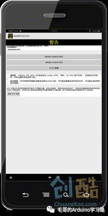
In the “Settings” page, there is a button for “Advanced Settings”; this is where you can control the quadcopter via Bluetooth. You will see a big yellow warning telling you that this feature is not yet perfect, and you need to know what you are doing, hee hee. There are two fun features here: “Follow Me” and “Heading Follow”. The interface clearly indicates that you need to uncomment certain lines in the source code to enable these features. As for how to modify the source code, that would be a big pit to explain.
In the “Advanced Settings”, there are two control modes: Model control New and Model control Old. The Model control New feature allows you to control the quadcopter directly with a large disk for forward, backward, left, and right movements, while Model control Old resembles a traditional remote control with two joysticks controlling throttle, pitch, roll, and direction. Additionally, there is an “AUX Control” for switch control. If you want to control the quadcopter entirely via Bluetooth, you will encounter unlocking issues. My method is to set one of the AUX1 switch states to unlock “ARM” in the PC’s MultiWiiConf, allowing you to use the Bluetooth control interface to unlock. But be careful; unlocking will make it fly away!
Download: MultiWii EZ-GUI.app
Step 10: Final Important Statement
This project is indeed suitable for those with RC modeling experience, aged 14 and above, as there are many pitfalls!
Finally, I recommend bookmarking a few websites, namely the MWC official website and the main thread of MWC on RCGroups forum, for the latest upgrade information and player discussions.