
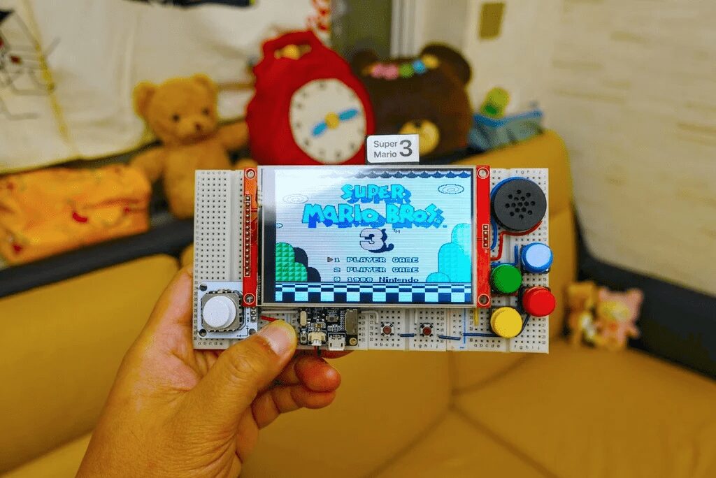
Currently, most NES emulators require the use of some C compiler (such as esp-idf) for manual command line builds, which is a significant barrier for beginners.
This week, I will share how to create a portable NES (Nintendo Entertainment System) gaming console using Arduino IDE.
The NES gaming console is a home video game console released by Nintendo in 1985. NES stands for “Nintendo Entertainment System”, also known as the “Famicom”. The console was popular worldwide in the 1980s and 1990s and made significant contributions to the development of the gaming industry.
The NES uses cartridges as game media, allowing players to run various games by inserting the cartridges. The design of the console’s controller is also very classic, including a directional pad, two buttons A and B, and two function buttons for select and start.
Many classic games such as “Super Mario Bros”, “The Legend of Zelda”, “Dungeons & Dragons”, and “Metroid” were first released on the NES. Even today, many players still enjoy playing classic games on the NES, and the influence of this console continues to this day.
Materials List
-
4.0 inch ST7796S SPI LCD module
-
Four 400-hole breadboards
-
TTGO T8 v1.7 ESP32 development board
-
MAX98357 I2S amplifier module
-
PCB-mounted mini speaker
-
PSP analog joystick module
-
Six button modules
Step 1: What is Nofrendo?
Nofrendo is a great NES emulator that can run at full speed on older Pentium systems, with decent sound support and good compatibility.
Nofrendo was developed by Matthew Conte in the last century and can run on Windows, Unix, and BeOS. Since the implementation has been generalized to support different platforms, many developers have started to develop NES emulators for other platforms based on it.
References:
<span>http://www.baisoku.org</span>
<span>https://www.zophar.net/nes/nofrendo.html</span>
<span>https://github.com/adafruit/nofrendo_arcada</span>
<span>https://github.com/espressif/esp32-nesemu</span>
Step 2: Arduino-nofrendo
In 2018, Github user rickyzhang82 pushed the original source code of Nofrendo to Github. I have forked the repository and converted it to a layout compatible with Arduino libraries. Simply implement all the functions declared in <span>osd.h</span> to make it work.
Theoretically, if there is enough RAM and processing power, this library can be used on any Arduino platform. Since Espressif has proven that the ESP32 can run Nofrendo, I developed an esp32-nofrendo example based on their sample code in the examples folder.
References:
<span>https://github.com/rickyzhang82/nofrendo</span>
<span>https://github.com/moononournation/arduino-nofrendo</span>
Step 3: Display Options
To support as many display variations as possible, I changed the display implementation to use Arduino_GFX. Now it even supports large 4-inch 320×480 displays like the ST7796.
Here are the display variations supported by Arduino_GFX that can apply to Nofrendo resolutions:
-
HX8347C 240 x 320 -
HX8347D 240 x 320 -
HX8352C 240 x 400 (16:9) -
HX8357B 320 x 480 -
ILI9341 240 x 320 -
ILI9481 320 x 480 18-bit color -
ILI9486 320 x 480 18-bit color -
ILI9488 320 x480 18-bit color -
M5Stack 240 x 320 -
R61529 320 x 480 -
ST7789 240 x 320 -
ST7789 240 x 240 -
ST7796 320 x 480
Note:
The 320 x 480 display requires cropping the original 256 x 240 resolution to 240 x 214, then scaling it up to 480 x 320.
Width is scaled by two times, height by 1.5 times, drawing three lines for every two original lines. The third line can repeat the second line or simply retain the background color of the third line.
Detailed implementation can be found in <span>display.cpp</span><span>.</span>
Step 4: Audio Options
Currently, arduino-nofrendo supports (in fact, arduino-esp32 supports) two audio output methods:
-
Built-in DAC – The ESP32 has two 8-bit DAC (Digital to Analog Converter) channels, connected to GPIO25 (Channel 1) and GPIO26 (Channel 2). Since the output is very weak, an additional audio amplifier is still needed for speaker output. -
External I2S DAC module – Just connect three signal wires and power to the I2S amplifier module, which can complete the work of both DAC and audio amplifier in the same module.
Note:
The built-in DAC only has 8-bit resolution and there is excessive static noise (hiss), which can be mitigated by using an external I2S amplifier module (since the external module can provide better signal-to-noise ratio and dynamic range).
Step 5: Controller Options
Currently, arduino-nofrendo supports three types of controllers:
-
GPIO input – Simply map each controller button to a GPIO, with an option to map the arrow keys to a two-axis analog joystick -
I2C M5Stack CardKB mini keyboard https://m5stack.com/products/cardkb-mini-keyboard -
I2C BBQ10 keyboard https://github.com/arturo182/BBQ10KBD
Coming soon:
-
More I2C devices, such as I2C game controllers -
Bluetooth devices, such as Bluetooth game controllers and Bluetooth keyboards
Note:
The default arduino-esp32 I2C interface connects to GPIO 21 (SDA) and 22 (SCL).
Step 6: File System Options
Nofrendo stores three types of files in the file system:
-
ROM file <span>*.nes</span>– Game -
Game save file <span>*.sav</span>– When you save in the game, data is backed up to this file -
State file <span>*.ss[0-9]</span>– When you use Nofrendo’s save state feature, data is stored in these files
Currently, arduino-nofrendo supports (in fact, arduino-esp32 supports) three types of file systems:
-
SPIFFS – Usually the last partition of ESP32 flash memory -
SD – Arduino standard SPI mode SD card interface -
SD_MMC – Native 1-bit or 4-bit SD mode SD card interface
Note:
Testing with SPIFFS is the simplest method, but backing up save and state files in SPIFFS can be more difficult. SD or SD_MMC is more suitable for long-term use. Additionally, as demonstrated in the video above, you can treat the SD card as a game cartridge, simply swapping the SD card to change games.
Step 7: Software Preparation
Arduino IDE
If you haven’t installed Arduino IDE yet, please download and install:
<span>https://www.arduino.cc/en/main/software</span>
ESP32 Support
Follow the installation instructions to add ESP32 support if not installed yet:
<span>https://github.com/espressif/arduino-esp32</span>
Note: Please use arduino-esp32 version 1.0.6 for this project, newer versions may not compile successfully
Arduino ESP32 Filesystem Uploader
Follow the installation steps to install Arduino ESP32 filesystem uploader if not installed:
<span>https://github.com/me-no-dev/arduino-esp32fs-plugin</span>
Arduino_GFX Library
Download the latest Arduino_GFX library: (Click “Clone or Download” -> “Download ZIP”)
<span>https://github.com/moononournation/Arduino_GFX</span>
Import the library in Arduino IDE. (Arduino IDE “Project” menu -> “Include Library” -> “Add .ZIP Library” -> Select the downloaded ZIP file)
Arduino Nofrendo Library
Download the latest Arduino Nofrendo library: (Click “Clone or Download” -> “Download ZIP”)
<span>https://github.com/moononournation/arduino-nofrendo</span>
Import the library in Arduino IDE as well. (Arduino IDE “Project” menu -> “Include Library” -> “Add .ZIP Library” -> Select the downloaded ZIP file)
Step 8: Breadboard Prototype
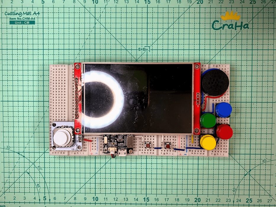
Before making your own portable Arduino NES console final version, let’s first do a PoC (Proof of Concept) with a breadboard prototype.
Step 9: Breadboard Modification
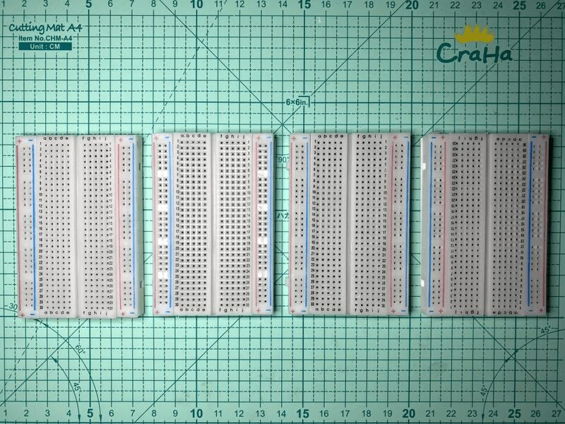
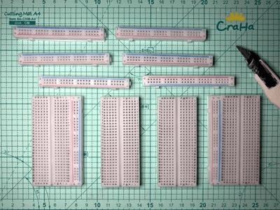
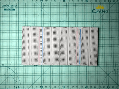
The 4-inch LCD is a relatively large size, and we need to combine four 400-hole breadboards together. However, eight power rails are too many, so we only keep two.
Step 10: TTGO T8 V1.7 Modification
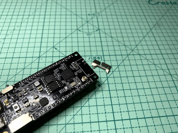
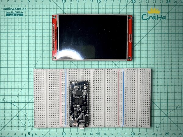
Combining four 400-hole breadboards can accommodate the 4-inch LCD, but there is still not enough space left for an ESP32 development board. Therefore, we need to hide part of the ESP32 development board beneath the LCD. At the same time, we will also hide the wiring under the LCD to make it neater.
However, I found that the 3D antenna of the TTGO T8 V1.7 cannot be placed under the LCD. Since the NES console does not require internet access, I simply removed it…
Note:
-
The WiFi signal can still be routed to an external antenna via the IPEX connector later -
Bluetooth device connections also require an antenna
Step 11: LCD Modification
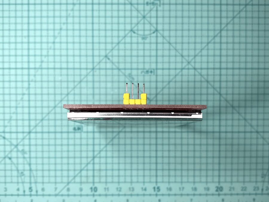
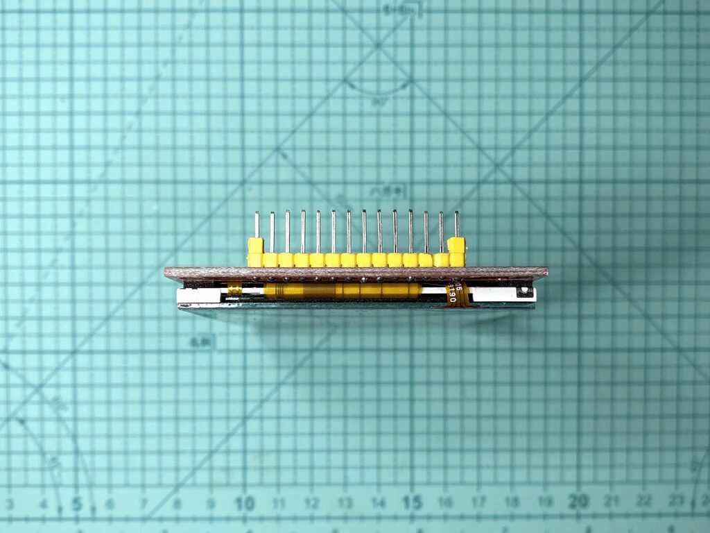
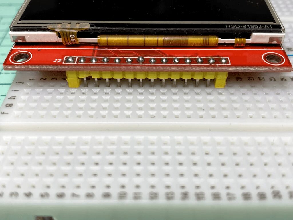
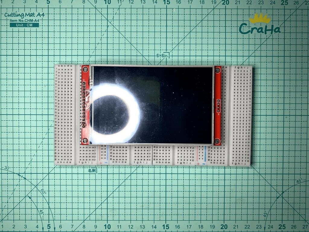
-
Solder the SD pin header -
Optional operation: re-solder all LCD pins to extend the pins slightly to the breadboard -
Insert extra plastic spacers to leave more space between the breadboard and the LCD
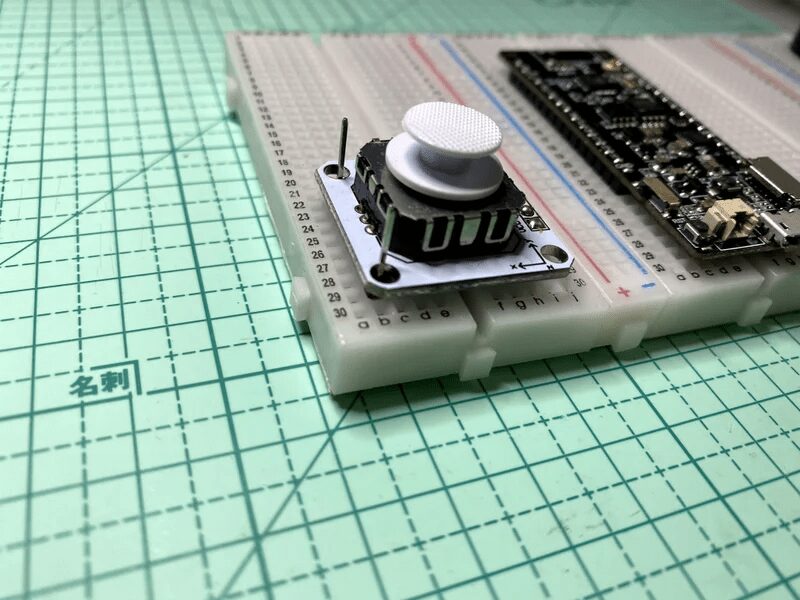
Step 12: Fix the Analog Joystick
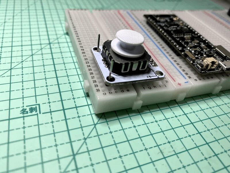
The side of the analog joystick with pins can be fixed very well on the breadboard, but the other side needs some extra pins to secure it to the breadboard.
Step 13: I2S Amplifier Module Modification
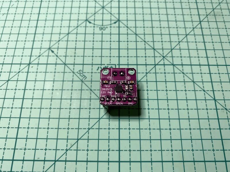
The speaker connector of the I2S amplifier module does not have a 2.54mm pitch (the size of breadboard holes), so the pin header needs to be bent slightly for easier soldering.
Step 14: Layout Design
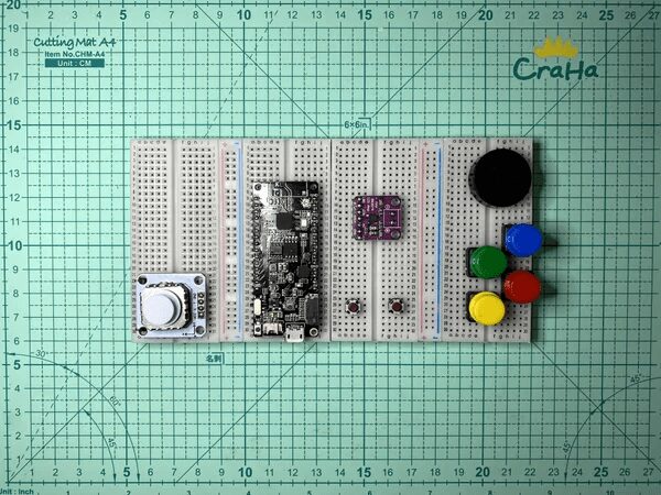
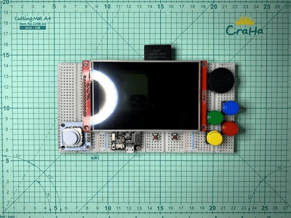
Before the actual wiring on the breadboard, we first design the layout of all components and carefully check whether the positions of all components conflict with the LCD.
Step 15: Pin Mapping Design
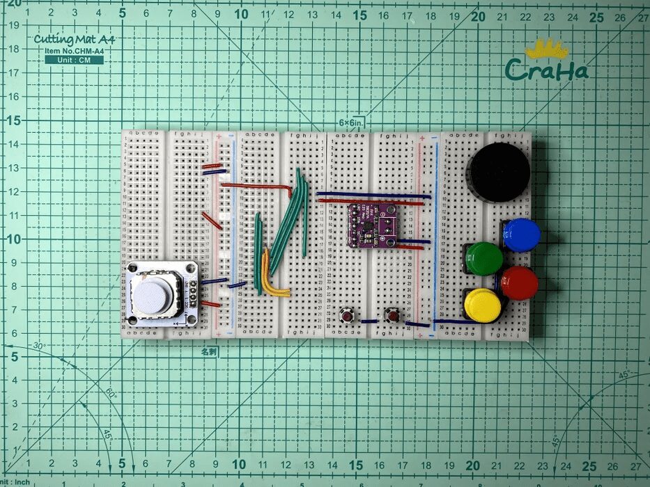
This step is optional, just to make the wiring neater (since all wires are hidden behind the LCD, it is not necessary).
Most ESP32 interfaces can be remapped to any GPIO pin, except for SD_MMC. Since the TTGO T8 v1.7 already has the SD card slot connected to the SD_MMC interface, I want to reuse those pins to connect to the LCD SD card slot.
I used some breadboard wires below the development board to redirect some GPIOs to other breadboard strips, making the entire layout look neater:
-
Analog joystick pins GPIO 34 and 35 to the lower left corner
-
SD_MMC pins GPIO 13, 15, 2, and 14 to the upper right corner
-
Start and select button pins GPIO 26 and 27 to the lower right corner
-
3v3 connected to two power strips
-
GND connected to power strips
-
Analog joystick pins GPIO 34 and 35 connected to the lower left
-
SD_MMC pins GPIO 13, 15, 2, and 14 connected to the upper right
-
Start and select button pins GPIO 26 and 27 connected to the lower right
-
3v3 connected to two power plugs
-
GND connected to power plugs
Note:
SPI displays usually require connecting seven GPIO pins, which are CS, RESET, D/C, SCK, MOSI, MISO, and LED. To reduce the number of GPIO uses to three, some arrangements were made:
-
CS grounded, indicating always enabled -
Reset connected to ESP32 reset, LCD resets when ESP32 resets -
MISO not connected, no need to read data from LCD -
LED connected to VCC, LCD backlight always 100% on
Step 16: Breadboard Wiring
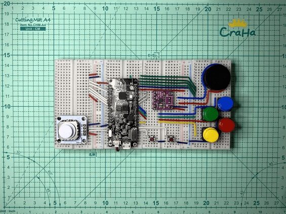
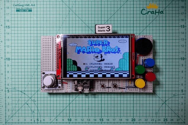
Here is the summary of connections:
ESP32
VCC -> LCD VCC & LED, I2S amplifier module VCC, joystick VCC
GND -> LCD GND & CS, I2S amplifier module GND, joystick GND, all button GND
RST -> LCD RST
GPIO 34 -> Joystick vertical analog
GPIO 35 -> Joystick horizontal analog
GPIO 32 -> LCD D/C
GPIO 33 -> LCD MOSI
GPIO 25 -> LCD SCK
GPIO 26 -> Button Start
GPIO 27 -> Button Select
GPIO 23 -> Button X
GPIO 18 -> Button Y
GPIO 5 -> Button A
GPIO 4 -> Button B
GPIO 14 -> SD SCK
GPIO 13 -> SD CS
GPIO 15 -> SD MOSI
GPIO 2 -> SD MISO
GPIO 22 -> I2S amplifier module BCLK
GPIO 21 -> I2S amplifier module WCLK (or LRC)
GPIO 19 -> I2S amplifier module DOUT (or DIN)
I2S amplifier module GAIN -> 100 ohm resistor -> GND (optional 15 dB gain)
I2S amplifier module +ve -> Speaker +ve
I2S amplifier module -ve -> Speaker -ve
Step 17: Optional Battery
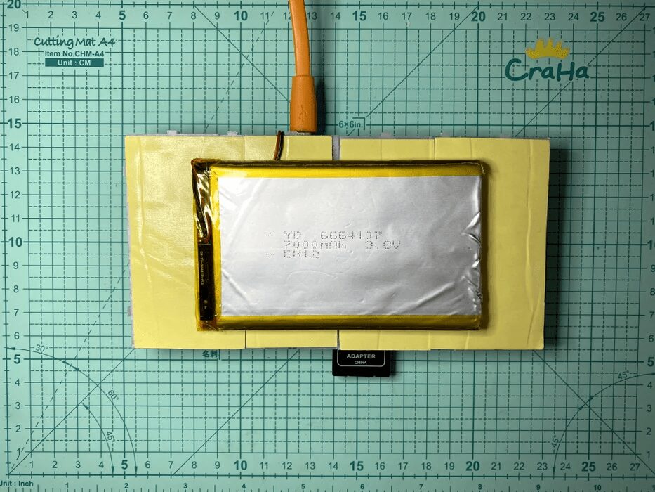
The TTGO T8 v1.7 development board has a built-in lithium battery charging and voltage regulation circuit. Connecting a lithium battery can make the console more portable, but it is not necessary for prototyping.
There is a large flat area behind the breadboard where a very large lithium battery can be placed.
Step 18: Program
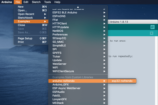
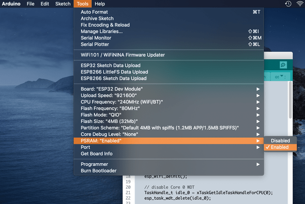
The steps to operate are as follows:
-
Connect the device’s USB cable -
Open Arduino IDE -
Open the esp32-nofrendo example code (“File” -> “Examples” -> “arduino-nofrendo” -> “esp32-nofrendo”) -
Check the configuration parameters in <span>hw_config.h</span>and<span>display.cpp</span>, default parameters are set for this breadboard -
Press the “Upload” button in Arduino IDE
Note:
Sometimes you need to remove the SD card to upload successfully.
Step 19: ROM
If you don’t have any NES rom files on hand, you can find many homemade NES roms online, such as:
<span>http://www.nesworld.com/article.php?system=nes&data=neshomebrew</span>
I have chosen a simple game called “Chase” for the esp32-nofrendo example in the “Best Homemade Nintendo Entertainment System Games”.
Note:
Also recommended is a homemade shooting game called “BLADE BUSTER”, but the rom size may not be suitable for development boards without PSRAM. (Nofrendo needs to load the rom file into memory)
Step 20: Upload ROM Files
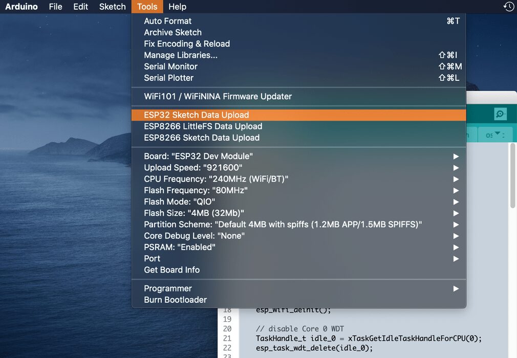
The default <span>hw_config.h</span> parameter is set to use the SD file system, just copy the ROM file <span>*.nes</span> to the SD card and insert it to make it work.
If changed to use the SPIFFS file system, the esp32-nofrendo example already includes a “Chase.nes” ROM file in the data folder.
Simply select the “Tools” menu in Arduino IDE -> “ESP32 Sketch Data Upload” to upload the ROM file to ESP32 SPIFFS.
You can also copy the ROM file to the data folder and upload it.
Note:
At this point, the esp32-nofrendo example will find the first <span>*.nes</span> file and load it.
Step 21: Save and Load State
Saving and loading states, also known as infinite recovery, is a simple cheat technique that can help you play games more easily.
The NES does not have X and Y buttons, and we will use them as buttons for saving and loading states.
Note:
Nofrendo has designed 10 save and load state slots, but currently, arduino-nofrendo can only use the first slot (slot 0).
Step 22: Pre-built ESP32 Consoles
Currently, there are few pre-built ESP32 development devices designed as gaming consoles on the market, such as:
-
TTGO T-Watch + Game Module -
ODROID-GO -
M5Stack + M5Stack CardKB
Step 23: TTGO T-Watch + Game Module
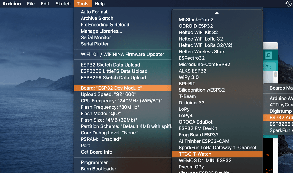
-
Open the esp32-nofrendo example code (“File” -> “Examples” -> “arduino-nofrendo” -> “esp32-nofrendo”) -
Select “TTGO T-Watch” (“Tools” -> “Board” -> “TTGO T-Watch”) and press the upload button -
Upload data (“Tools” -> “ESP32 Sketch Data Upload”)
Reference:
<span>https://t-watch-document-en.readthedocs.io/en/latest/introduction/index.html</span>
Step 24: ODROID-GO
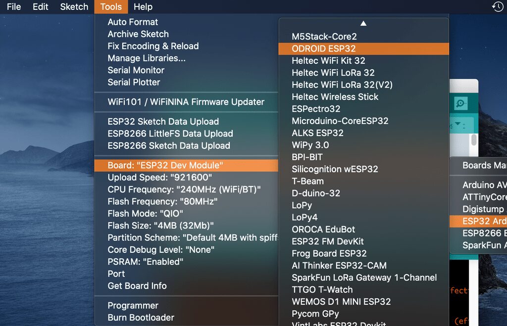
-
Open the esp32-nofrendo example code (“File” -> “Examples” -> “arduino-nofrendo” -> “esp32-nofrendo”) -
Select “ODROID ESP32” (“Tools” -> “Board” -> “ODROID ESP32”) -
Press the upload button
Reference:
<span>https://www.hardkernel.com/shop/odroid-go/</span>
Step 25: M5Stack + M5Stack CardKB
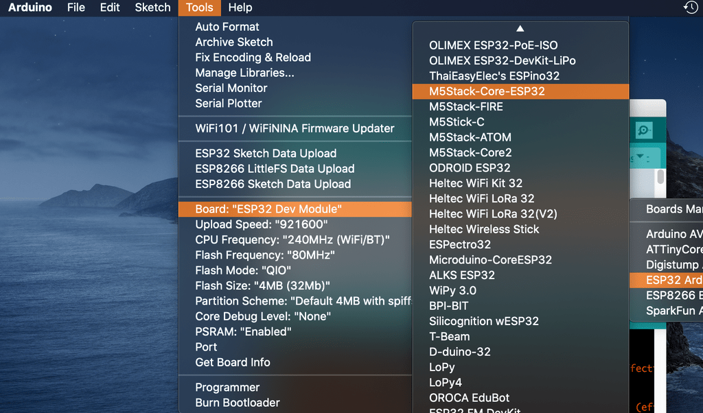
-
Open the esp32-nofrendo example code (“File” -> “Examples” -> “arduino-nofrendo” -> “esp32-nofrendo”)
-
Select “M5Stack-Core-ESP32” (“Tools” -> “Board” -> “M5Stack-Core-ESP32”)
-
Press the upload button
Note:
The CardKB can only read one button press at a time, suitable for playing certain specific games.
Reference:
<span>https://m5stack.com/collections/m5-core</span>
<span>https://m5stack.com/products/cardkb-mini-keyboard</span>
Step 26: Start Enjoying Games
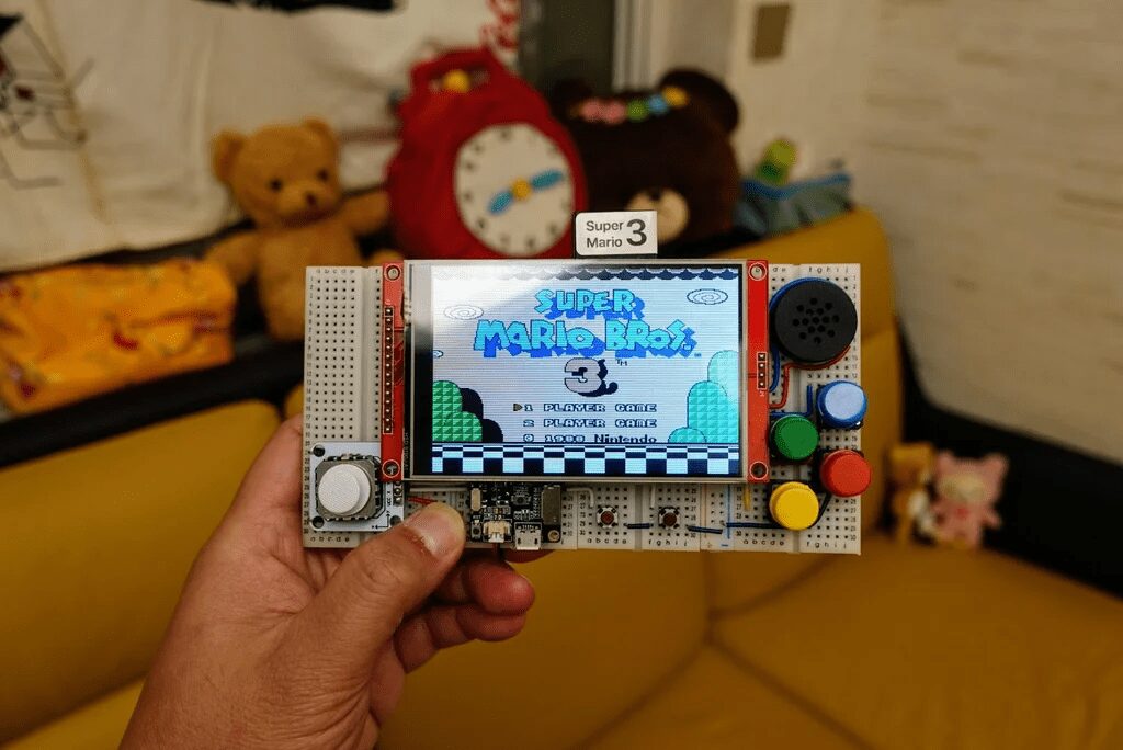
The Arduino IDE is a very user-friendly platform. The esp32-nofrendo example is just a starting point, and you can add more features to it, such as:
-
Touchscreen UI -
Game selection UI with artwork images like RetroPie -
Saving states while playing games -
State slot selection -
State saving with saves -
State browsing and loading UI with save previews -
Volume settings -
LCD backlight settings
Get started and make your own Arduino NES!
References
[1] Best Homemade Nintendo Entertainment System Games: http://www.nesworld.com/article.php?system=nes&data=neshomebrew_bestof
Original author: 陳亮
Original link: https://www.instructables.com/Arduino-NES/
Translation first published in: DF Maker Community
Reprint must indicate source information
Hardware Arsenal
DF Hardware Arsenal
Click to learn more👆
If you have anything to say, feel free to leave a comment below!
Previous Project Review
Understand the entire series of Raspberry Pi in one article!
Learn these 20 Linux commands to master your Raspberry Pi!
Raspberry Pi Cyberdeck with six screens, check it out!
“Light up” the Christmas tree with Raspberry Pi
Build a Raspberry Pi cloud server, portable in your pocket!
Make a “digital microscope” with Raspberry Pi
Spring is here, you need a retro-style Raspberry Pi camera
3D printed Raspberry Pi spider robot
Make a handheld computer with Raspberry Pi and ESP32!
Create a retro game console based on Raspberry Pi Zero
The most comprehensive! How to choose Raspberry Pi expansion boards? One video to solve it!
Click to read👆