
Since Boston Dynamics’ Spot, quadruped robot dogs have become very popular.
The community previously shared a quadruped robot Pupper made with Raspberry Pi——《Can run, jump, and stroll, the little follower of Boston Dynamics Spot is here! Project is open source!》
Pupper’s little brother made with Arduino Uno——《Highly extensible, the little brother of the quadruped robot Stanford Pupper is here!》
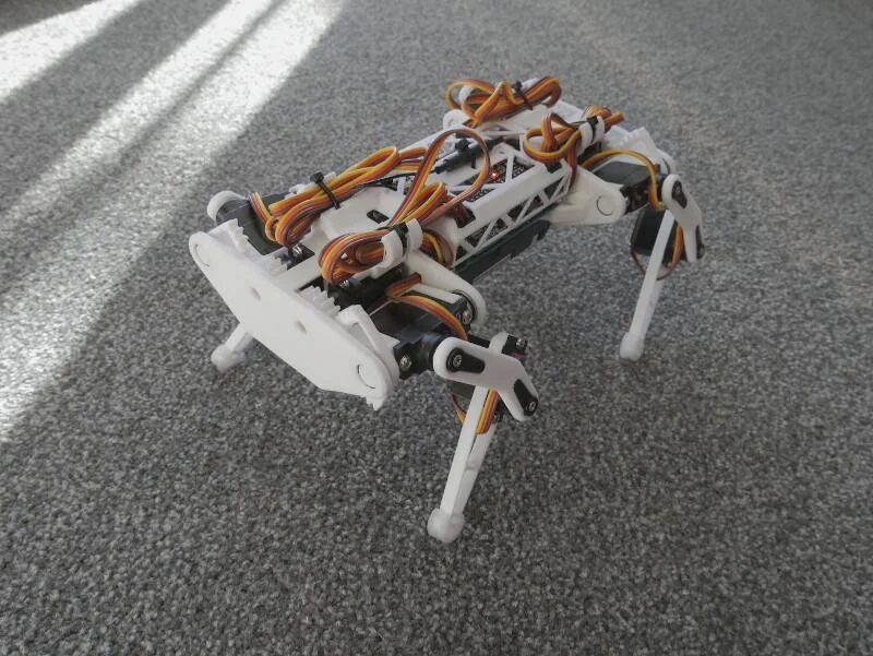
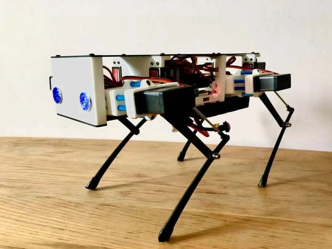
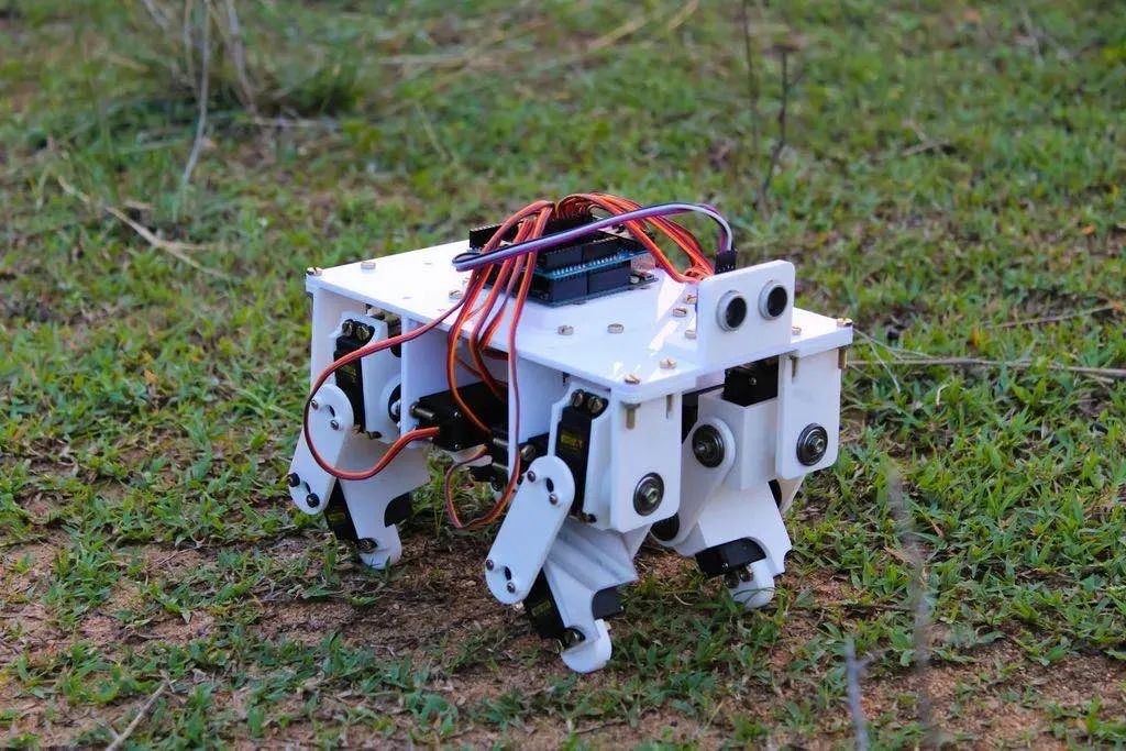
Today we share a small quadruped robot dog made using ESP32.
Features
-
Only requires ESP32 (no additional PWM I2C, Bluetooth modules, etc.) -
Arduino IDE -
Can be remotely controlled with just a phone or tablet -
Has a CLI interface for calibration and debugging -
Inverse kinematics code -
Configurable gait sequences
Electronics
-
1 x 38-pin ESP32 -
1 x 50x70mm prototype development board -
12 x TowerPro MG90D servos (using other servos may be troublesome due to size differences; you can check images of three different servos similar to MG90)
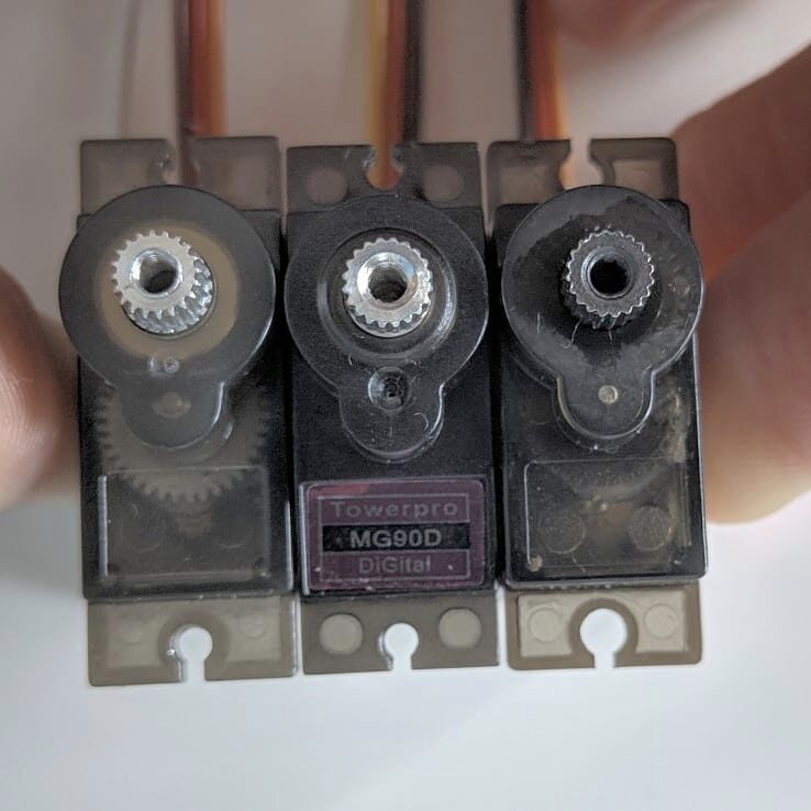
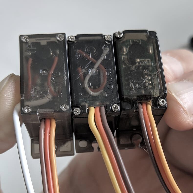
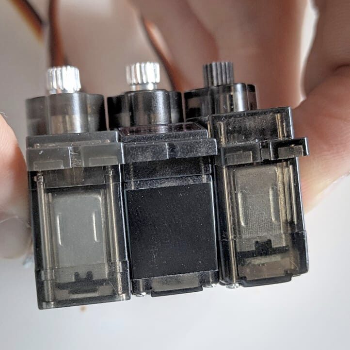
<<< Swipe left to see more >>>
-
1 x INA219 (optional) -
1 x MPU9250 (optional) -
3 x Mini360 (DC-DC buck converter modules) or similar products, 2 for front/back legs (or more), 1 for ESP32 -
1 x 18650 lithium battery holder for 2 components (try searching for “18650 battery holder SMT”). -
2 x 18650 lithium batteries -
Some capacitors
Others
-
8 x 8x12x2.5mm bearings -
4 x Dupont wire ties -
Use 502 glue (cyanoacrylate) to glue all components together
Printed Parts
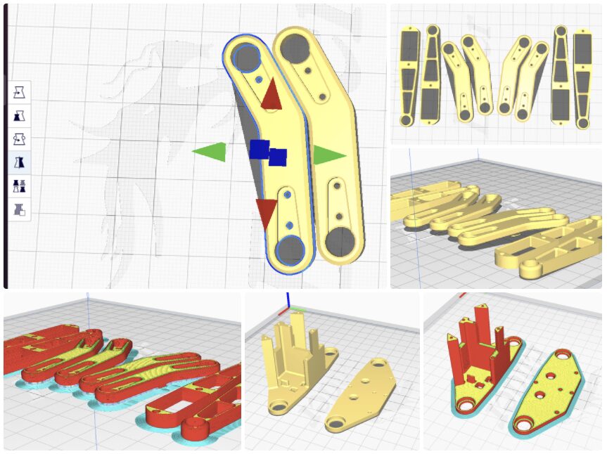
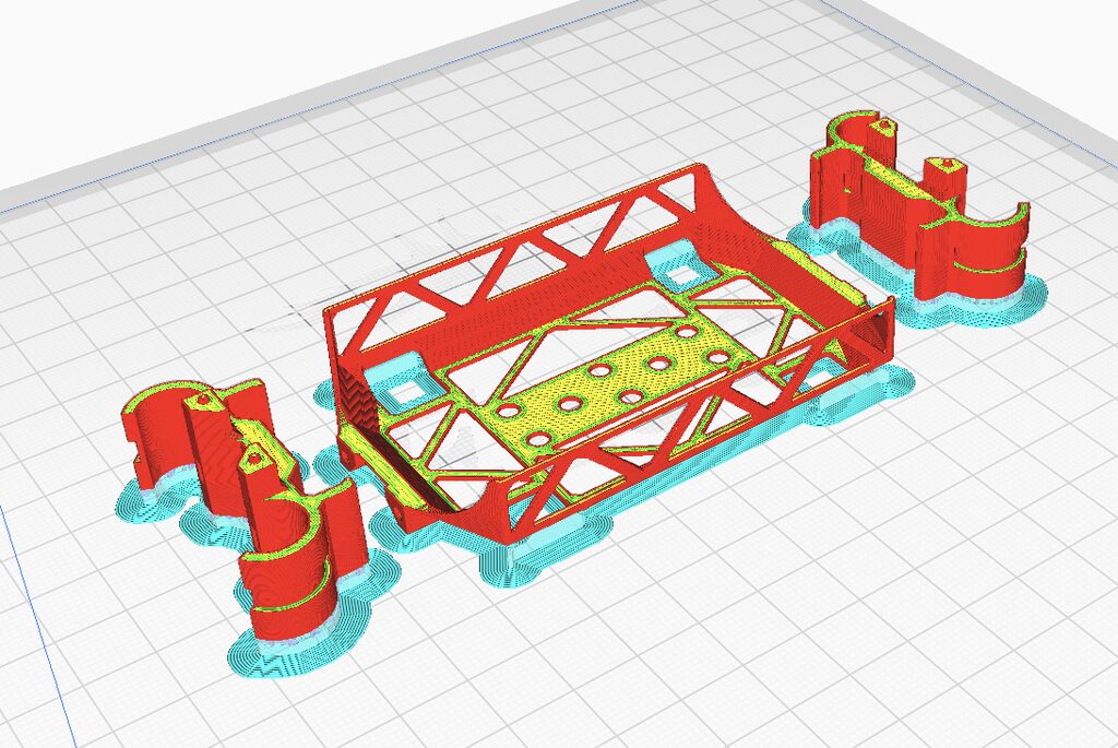
All STL files for printing can be downloaded at the end of the article.
Some parts are mirrored to ensure correct printing. Please pay attention to the images.
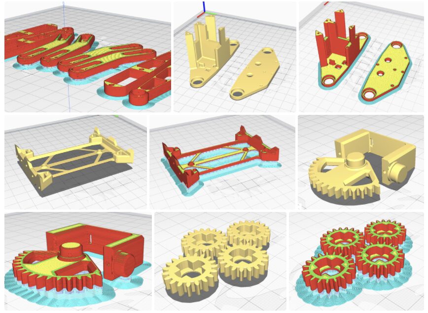
My printer had issues with the first layer thickness, which is the feet. The gears should be printed as perfectly as possible, so I added very small spacers to avoid this issue; you will see some parts “flying” over the surface, remember to enable support for it.
It is highly recommended to use the best quality printing parts, especially for the gear sections.
Complete list of parts to print:
-
1 x Body part -
2 x Top leg parts -
2 x Leg tops (mirrored) -
2 x Foot plates -
2 x Bottom leg parts (mirrored) -
4 x Shoulder part 1 -
4 x Shoulder part 2 -
2 x Leg bracket part 1 -
2 x Foot pipe fixer part 2 -
4 x Servo gears -
4 x Foot pipe shoes, print with flexible filament (optional) -
1 x Cover -
2 x Cover clamps
I used Ender 3 Pro, Cura, with supports and selected dynamic quality. The plastic is OPY’s PLA.
You can download it at https://www.thingiverse.com/thing:4822059 or at the end of the article.
Assembly
Preparation
Before starting, check if the bearings can be easily installed on the body and shoulder parts.
Also check if the holes on the shoulder and body parts are printed well, and if the servo Dupont wires (temporarily disconnected servo connectors) can fit inside.
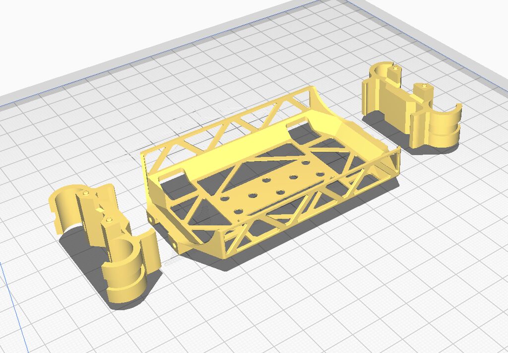
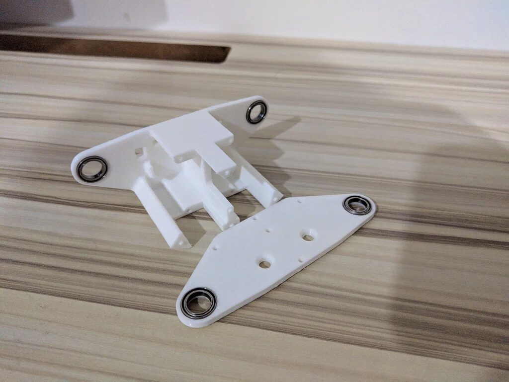
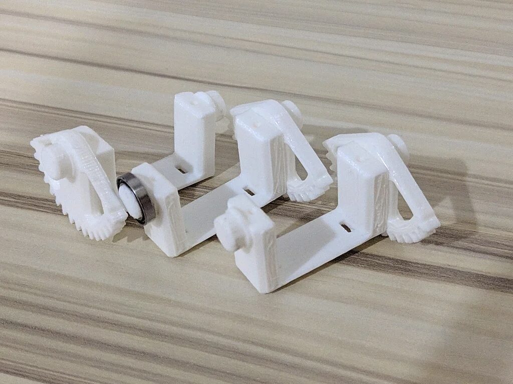
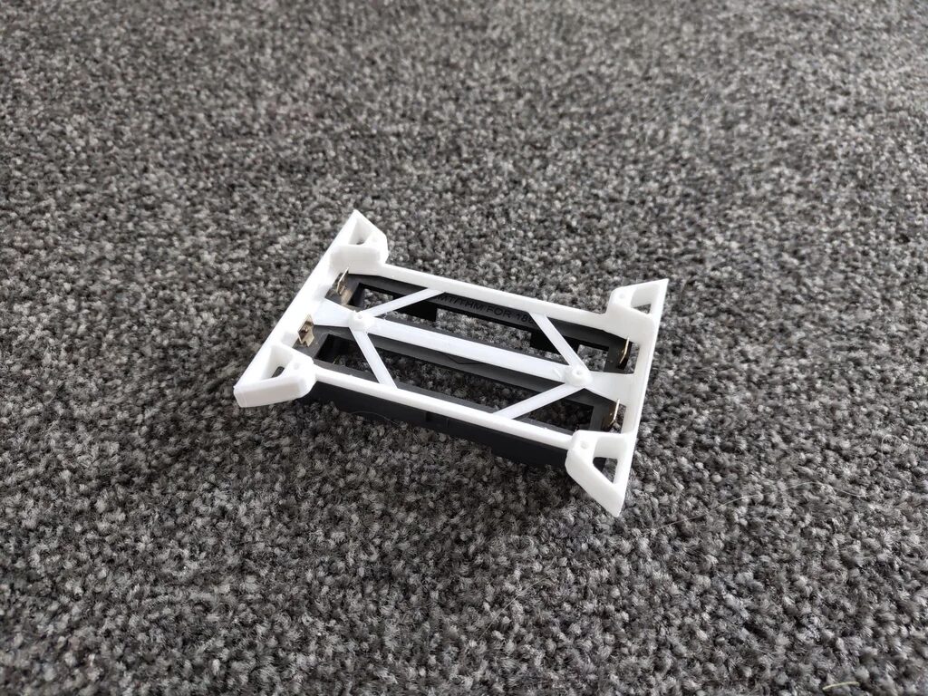
Start Assembly
I tried to make the body as light as possible since the small servos are not very powerful.
Ensure the gluing surfaces are flat; you can use a file for this. Ensure the parts connect without gaps.
Then glue them together as shown in the image above.
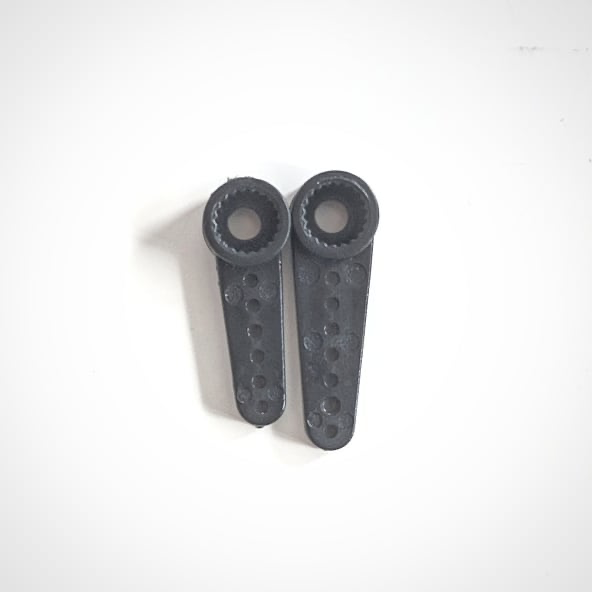
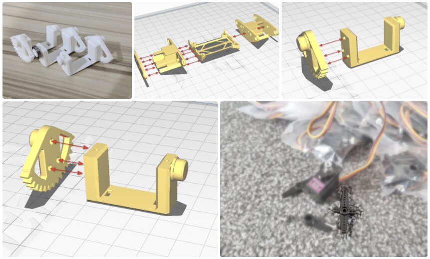
Servo Gears
Cut the servo angles (see image) to fit the servo gear parts and glue them together.
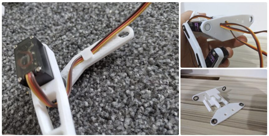
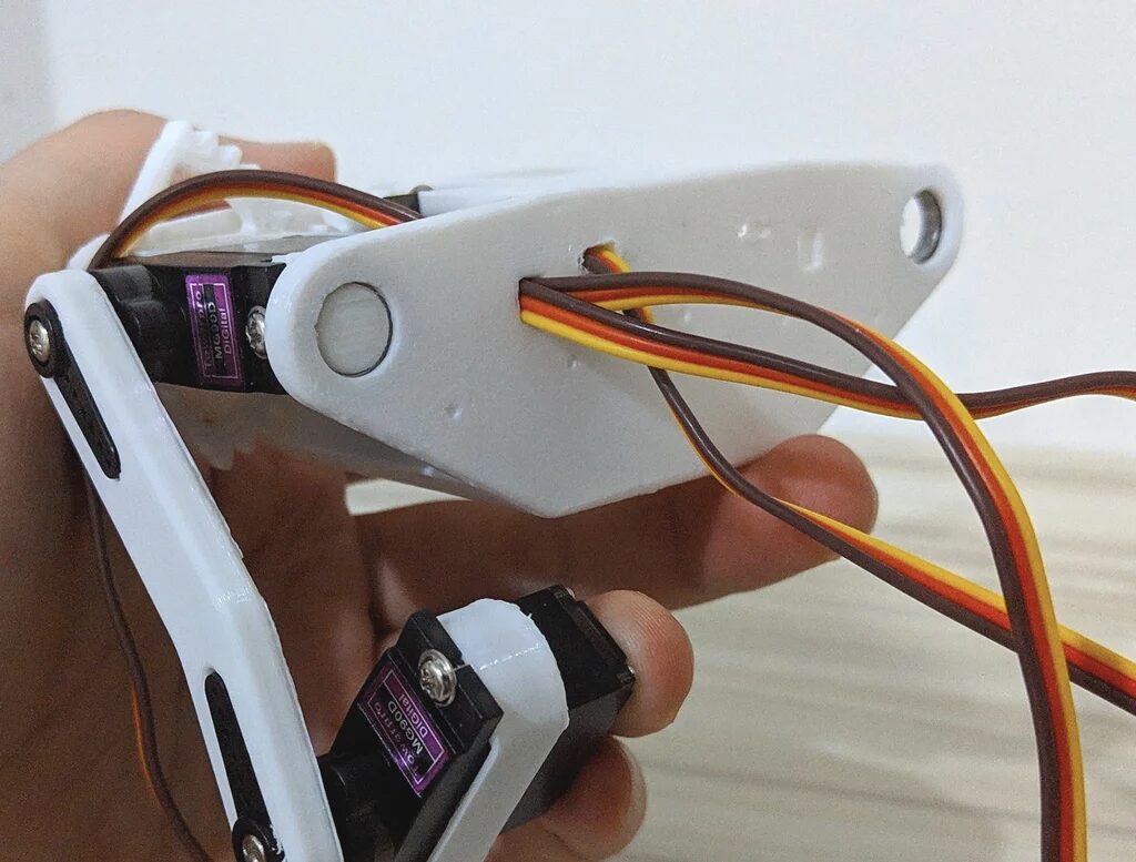
Legs
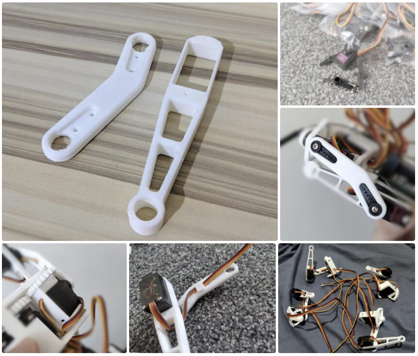
Glue the short servo angle onto the “top of the leg” part.
Insert the servo into the “bottom of the leg” and insert the Dupont wire as shown in the image.
Pass the Dupont wire of another servo through a hole in the “shoulder” part.
Repeat the above steps.
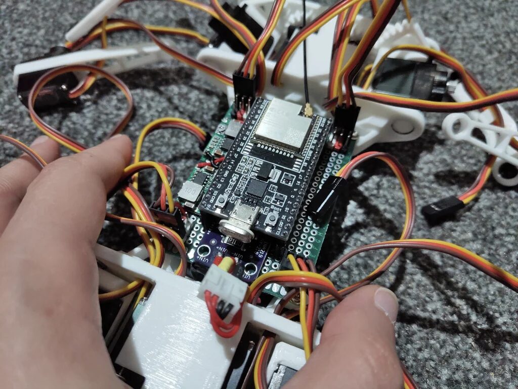
Assemble the Body and Legs Together
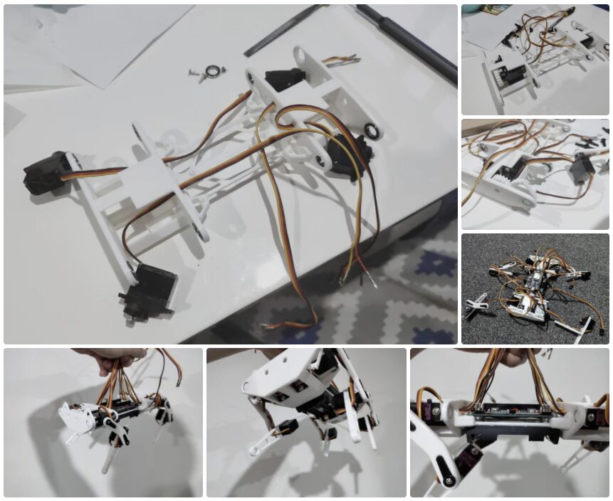
As shown in the previous images, pass all Dupont wires through the holes in the legs and body.
Use Arduino/ESP32 or a servo tester to set all servos to the middle position.
Install the “servo gears” onto the servos and insert the servos into the body. It might be a challenge to tighten them.
Press the “shoulder” part without a servo (but with Dupont wires) into the bearings.
Repeat the operation for other servos and parts.
At this point, we do not need to secure the legs with bolts; later we will need to calibrate the legs according to the instructions in my GitHub repository:
https://github.com/SovGVD/esp32-robot-dog-code
PCB Part
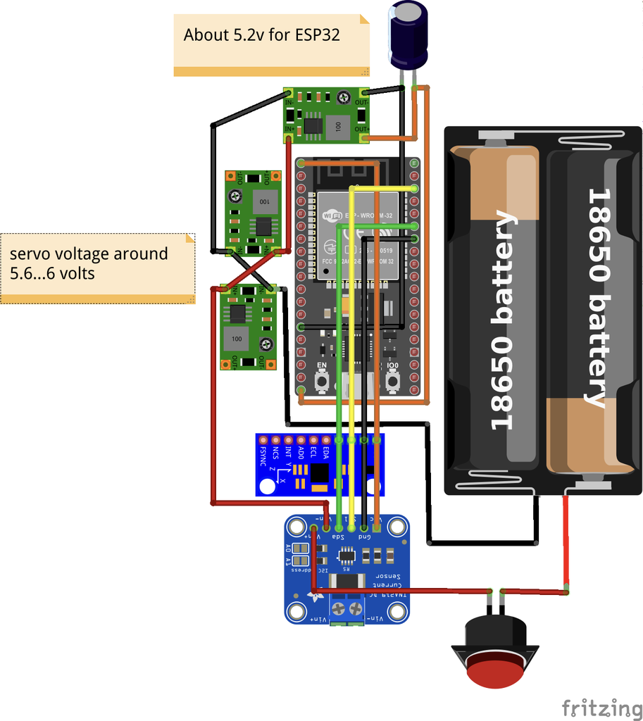
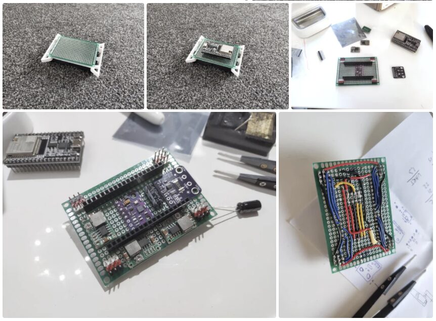
The PCB configuration is up to you. Below is just my approach.
The sensors are connected to the default I2C bus of the ESP32 (GPIO 21 and 22).
The servos are connected to:
-
Left Front: 25, 26, 27 -
Right Front: 16, 18, 17 -
Left Back (Rear): 13, 12, 14 -
Right Back (Rear): 4, 2, 15
You can reconfigure in the code, but ensure the ESP32 ISR library is supported.
Code
Install additional libraries on Arduino IDE:
-
ESP Async Web Server -
ESP32 ISR Servo -
MPU9250_WE -
INA219_WE
Set WiFi access point credentials:
-
Rename config_wifi.example.htoconfig_wifi.h -
Change APssidto any name for your robot, e.g.,SmallRobotDog -
Change APpassto a password (8 or more characters), such asMySup3rPassw0rd -
After uploading the code to ESP32, you should be able to find the WiFi SmallRobotDogwith your phone or tablet.
Open a browser, enter the URL http://192.168.4.1/, and you will see two virtual joysticks to control the robot dog.
I hope you enjoy it.
Original project English link: https://www.instructables.com/ESP32-Small-Robot-Dog/
Project Author: Gleb Devyatkin
This translation was first published in DF Maker Community
Hardware Arsenal
Click to learn more👆
If you have anything to say or corrections to the article translation, feel free to leave a comment below!
All the code and STL files involved in the project can be downloaded by replying “ESP32 Quadruped Robot Dog” in the public account!
Review of Previous Projects
▼ Can run, jump, and stroll, the little follower of Boston Dynamics Spot is here!
Click to read👆
▼ Highly extensible, the little brother of the quadruped robot Stanford Pupper is here!
Click to read👆