Follow+Star Public Account Number, don’t miss out on exciting content
In recent years, starting with Apple’s release of theAirPods, the true wireless headset market has seen rapid growth, and theTWS/OWS headset market has also experienced significant sales increases. The charging cases that accompanyTWS headsets have developed rapidly alongside the headsets. This article introduces a design for a charging case that utilizes single-wire bidirectional serial communication, which only requires twopogo pins to make contact with the headset for serial communication, enabling complex operations such as data exchange with the headset, thus making the Bluetooth headset charging case more user-friendly and intelligent, enhancing user convenience.
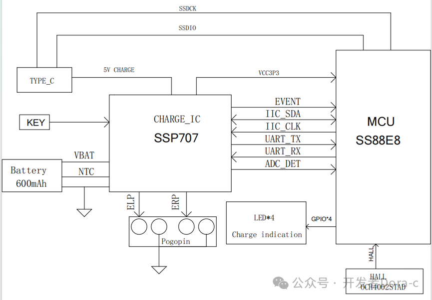
Overall Design of the Charging Case Hardware1.Main Control ChipMCU1. The main control of the charging case uses the Shengsheng MicroelectronicsSS86F8 51core architecture general-purpose microcontrollerMCU2. 8bit enhancedMCU, 12KB Code Flash, 128B EEPROM, 192B Data RAM3. 316bit timers, capable of generating7 channels ofPWM4.Integrated1 half-duplex communicationUART interface 2.Power Management Chip(PMIC, POWER MANAGER IC)1.The power management chip uses Shengsheng Micro’sSSP707. It supportsIIC communication, multifunctionalPMIC (Power Management IC).2.Built-in carrier communication module, supporting various application scenarios.3.Supports5/0V communication,PLC communication,ELP/ERP voltage detection, light load detection, communication level conversion, and otherTWS related features.
3. Intelligent Charging Case Design Hardware Block Diagram
Overall Design of the Charging Case Software
1. Environment Setup
Keil C51, Shengsheng MicroSSW Flash Tool programming tool
2. Firmware Programming
Using4 wire programmingDCN, DAT, CLK, GND. It can be divided into online programming and offline programming
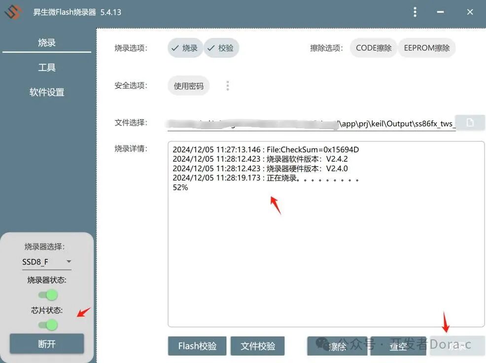
Online Programming
Using Shengsheng Micro’s online programming tool, connect the wiring to the charging case
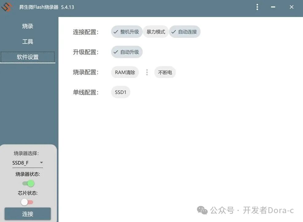
Click to connect, and after a successful connection, the computer will display the chip status as connected, then click to program
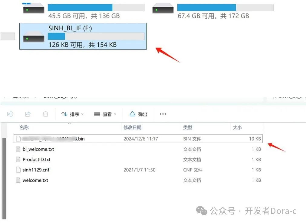
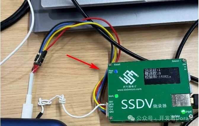
Offline Programming
Offline programming refers to directly deploying the firmware to the programmer, which will be recognized as a drive letter when plugged into the computer. Place the compiled firmwarebin file into the programmer’s drive letter
The programmer uses4 wire connection to connect to the base.Click the button on the programmer labeledUpdate to start programming
The green indicator light flashes to indicate that programming has started; if programming is successful, thepass light will turn on, and the display will show
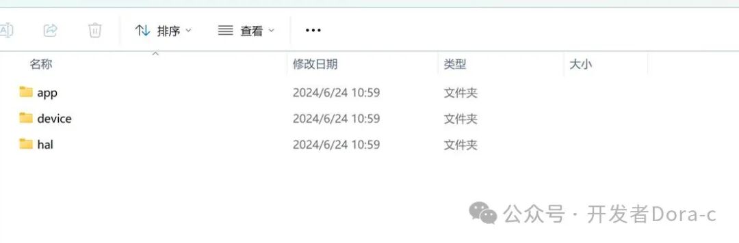
3. TWS Intelligent Charging Case DEMO Code Directory Structure
app — Stores application layer code (communication logic UI logic, etc.)
device — Driver layer code (key driver, Hall sensor driver NTC driver, etc.)
hal — Hardware abstraction layer code(GPIO TIMER UART IIC etc.)
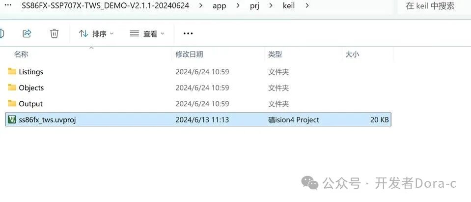
The project files are located inapp/prj/keil directory, open thekeil project
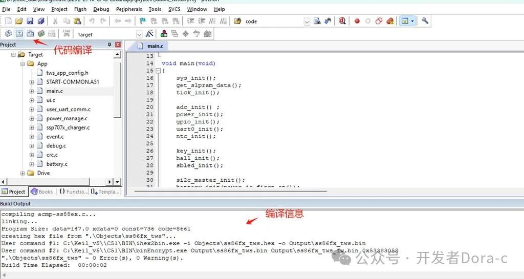
Usekeil C51 for code compilationbuild orrebuild
Charging Case Software Code Snippet Analysis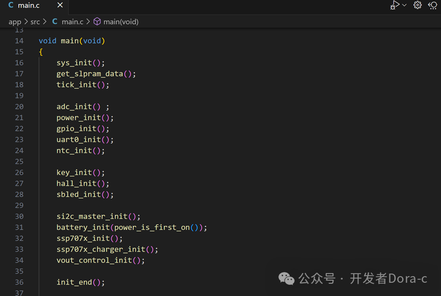 1. User Definitions
device-config-default.h file contains commonly used macro definitions
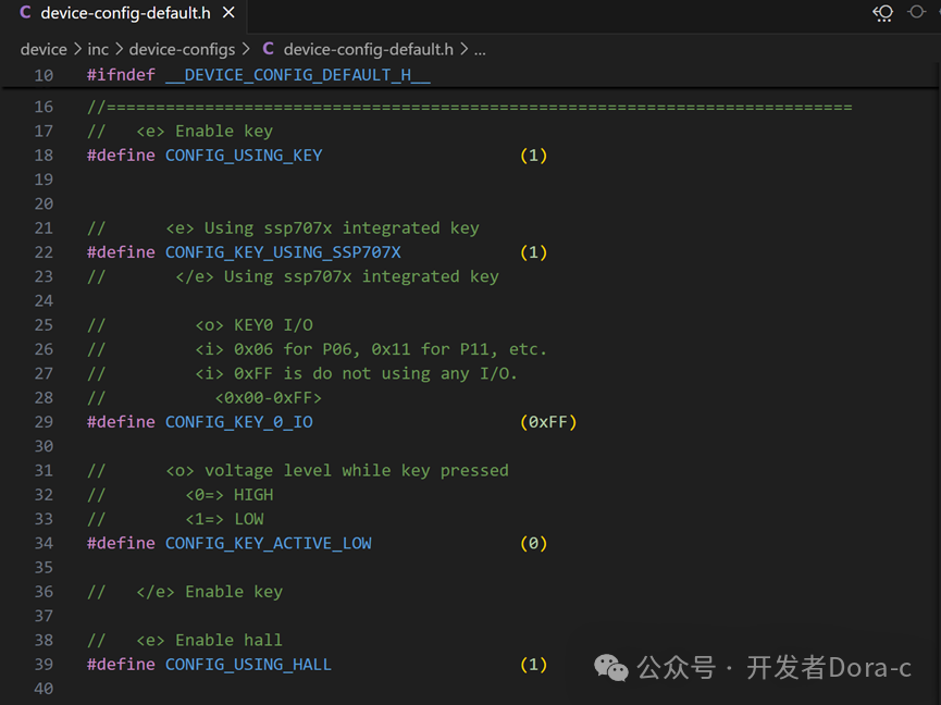
1. Key Definitions:
#define CONFIG_USING_KEY 1
#define CONFIG_KEY_USING_SSP707X 1
Key: The key is mounted on theSSP707X chip; use the GET_KEY_STATUS() function interface to sendIIC commands to check ifSSP707X is pressed.
2. Hall Effect Sensor Definitions
Defines whether to use the Hall effect sensor when the cover is opened, and defines the IO port used by the Hall effect sensor. P0_7
#define CONFIG_USING_HALL (1)
#define CONFIG_HALL_IO (0x07)
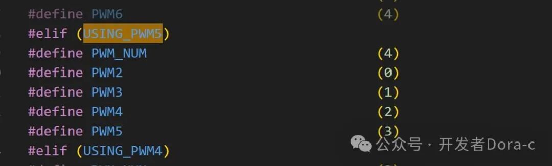
3.LED Control Definitions
#define CONFIG_USING_SBLED 1
#define USING_PWM5
UsingPWM2 PWM3 PWM4 PWM5 4 LEDs for lighting
4. Battery Display
#define CONFIG_USING_BATTERY 1
5. IIC Controller
#define CONFIG_USING_SI2C 1
Used to controlSSP707X
2. Initialization Complete
After initialization is complete, the timer will start, and each module will begin to process in a loop. The timer will create10ms,100ms,1s timing flags, which will be processed inmain withinwhile(1) to handle each timing flag.
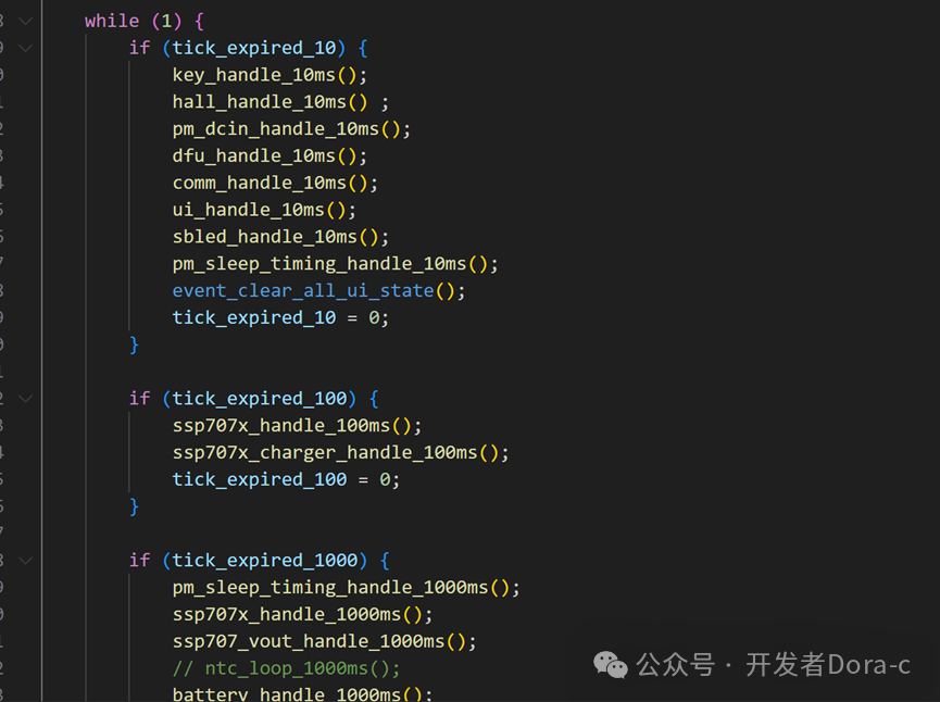
3. Each Module Timing Processing
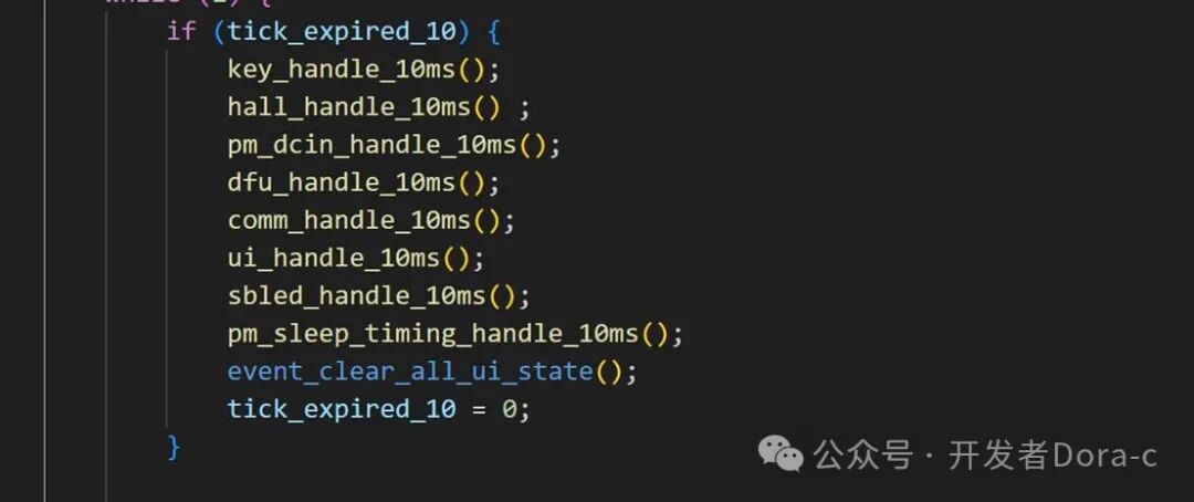
Taking10ms flag processing as an example, each module10ms calls its internal processing, usingevent_set_ui_state to setui_state flags, which are then used by other modules to perform corresponding processing based on theui_state flags.
1. 10ms Key Key Processing
void key_handle_10ms(void)
Check if pressed, thenkey_0_pressed_cnt++; Releasekey_0_pressed_cnt=0
Key Status:
– Short Press
key_0_pressed_cnt>5&& key_0_pressed_cnt<CONFIG_KEY_SHORT_PRESS_CNT
event_set_ui_state(EVENT_STATE_UI_KEY_CLICK)
– Long Press
key_0_pressed_cnt==CONFIG_KEY_LONG_PRESS_CNT
event_set_ui_state(EVENT_STATE_UI_EAR_PAIRING)
– Extended Long Press
key_0_pressed_cnt==CONFIG_KEY_LLONG_PRESS_CNT
event_set_ui_state(EVENT_STATE_UI_EAR_RESTORE)
2.10ms Hall Processing
void hall_handle_10ms(void)
IS_HALL_ON() to get the Hall sensor IO port status, withdebounce
event_set_ui_state(EVENT_STATE_UI_HALL_OFF)
event_set_ui_state(EVENT_STATE_UI_HALL_ON)
3.10ms USB Insertion(DC IN Processing)
void pm_dcin_handle_10ms(void)
Check if there isUSB·
event_set_ui_state(EVENT_STATE_UI_DCIN_IN))
event_set_ui_state(EVENT_STATE_UI_DCIN_OUT)
4.10ms DFU Processing
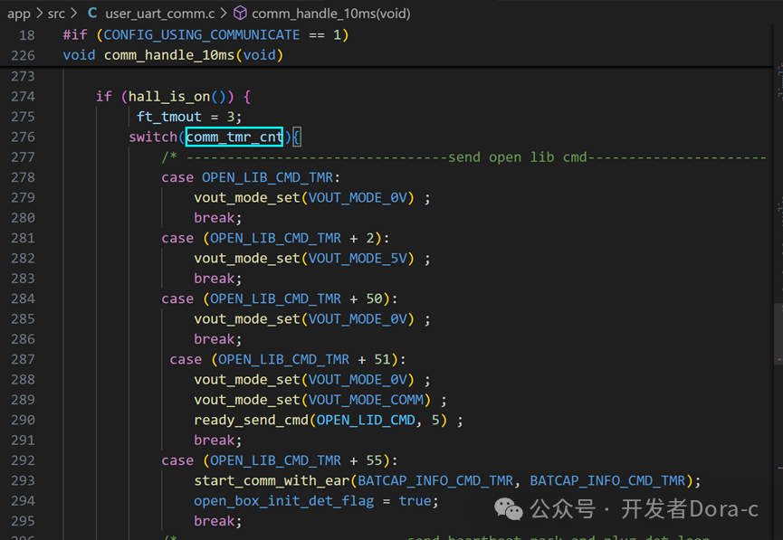
5.10ms Communication Module Processing
void comm_handle_10ms(void)
During communication, check for previoushall state change events, key events, light load and overload events
Based oncomm_tmr_cnt handle different tasks comm_tmr_cnt increments every10ms by++ action
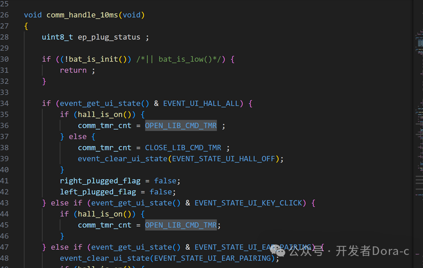
10ms communication module processing:
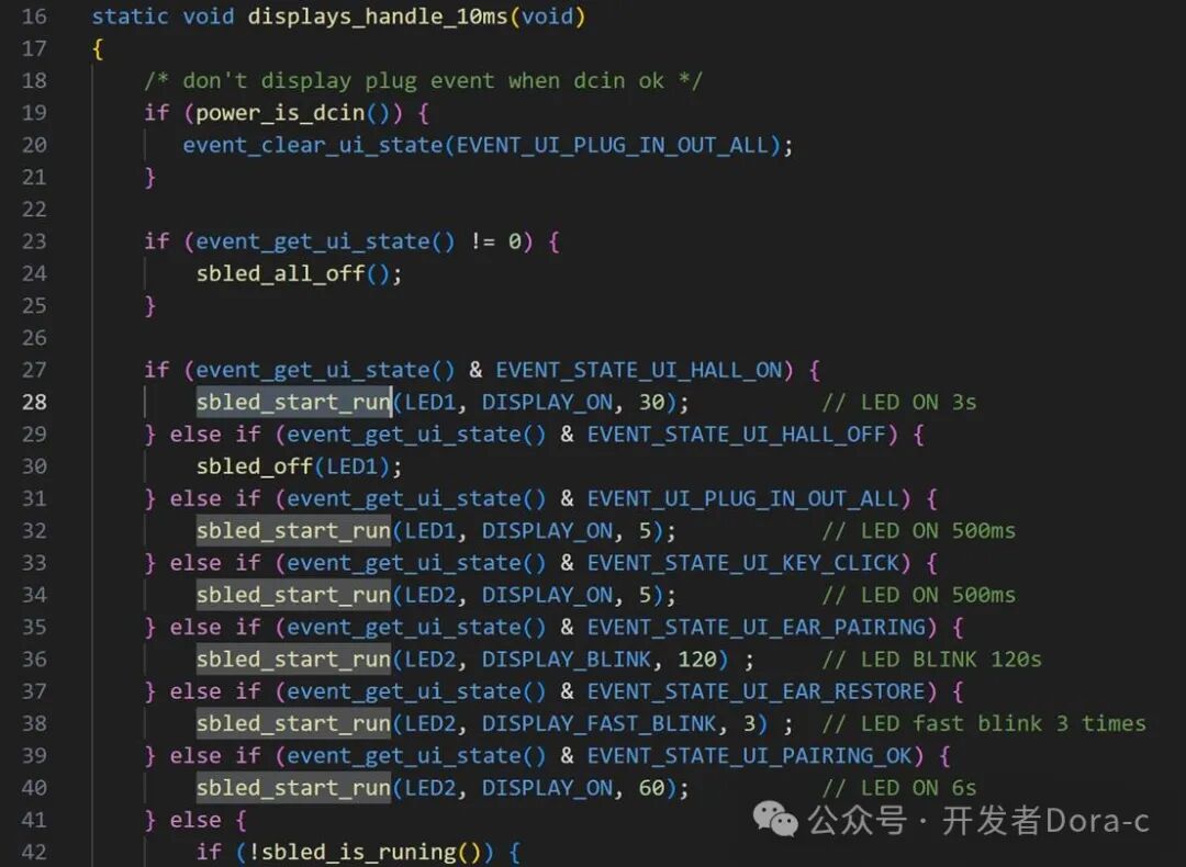
6. 10ms UI Module Processing
void displays_handle_10ms(void)
UI module retrieves theui_state set by other modules for LED light display processing: setled flashing pattern
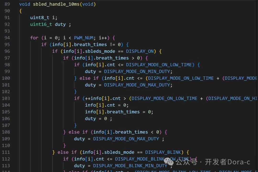
7. 10ms SBLED Module Processing
Based onui module settings for led patterns, perform light flashing
———— END ———–
Follow me, sharing more Bluetooth headset software development content