As people’s demands for automotive safety, comfort, exhaust emissions, and fuel economy become increasingly stringent, the amount of information exchanged between control units is growing, and the number of sensors and wires is rapidly increasing, making it more difficult to troubleshoot and repair. To ensure that the electronic systems in vehicles remain operational without taking up too much space, the CAN data bus has emerged.
1. Introduction to CAN Communication Network
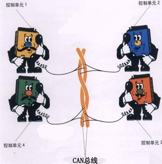
CAN stands for Controller Area Network. The CAN bus was developed by the German company BOSCH, connecting various control units in the vehicle to achieve reliable information sharing, significantly reducing the number of wiring harnesses in the vehicle.
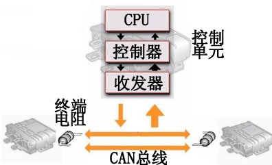
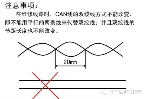
The CAN bus system mainly consists of control units, the CAN bus, and two terminal resistors. The control unit comprises a central processing unit (CPU), a controller, and a transceiver. The CAN bus uses twisted pair cables (CAN-L and CAN-H) to resist electromagnetic interference, and both terminal resistors are 120 Ω.
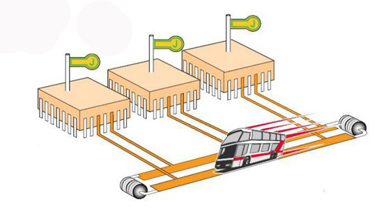
Data transmission on the CAN bus is like a conference call; one phone user (equivalent to a control unit) “speaks” data into the phone line (equivalent to the CAN bus), and other users “listen” to this data. Users interested in this data will utilize it, while others may choose to ignore it.
2. Fault Diagnosis of CAN Communication Network
When faults occur in the vehicle’s CAN communication network, the following steps can be taken to troubleshoot.
1. Use a fault detection device for testing. If unable to access the control unit or if there are fault codes starting with ‘U’ after entering the control unit, it generally indicates a fault in the CAN communication network.
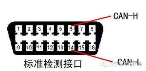
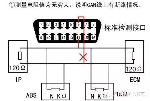
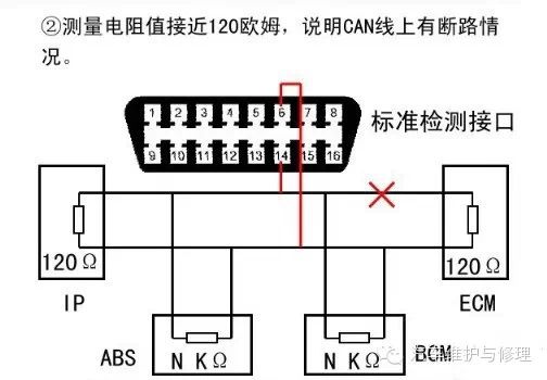
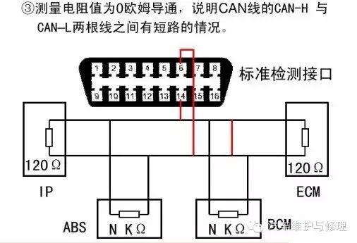
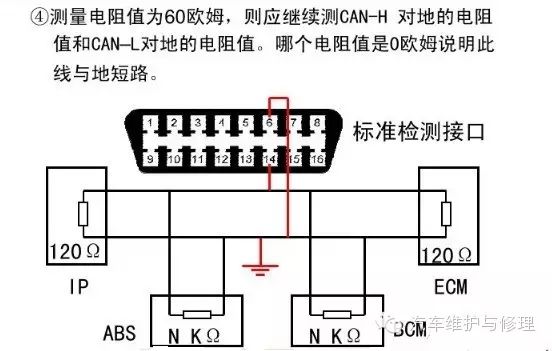
2. Disconnect the ignition switch and cut off the battery power for 5 minutes. Then, use a multimeter set to the 200 ohm resistance range to measure the resistance between pin 14 (CAN-L) and pin 6 (CAN-H) of the standard diagnostic interface. The standard resistance value should be 60 ohms (the parallel resistance of the two terminal resistors is 60 ohms).
Follow Us——“Automotive Maintenance and Repair” Magazine
ISSN: 1006-6489 CN 32-1438/U
Postal Code: 28-241
Website: www.autorepair.com.cn
Contact Phone: Editorial Department: 025-84803820
Business Department: 025-84825381