ver0.2
Introduction
We have begun to touch upon the software layer of power management. In this article, we will delve deeper into the internal architecture of power management software based on the previous discussion of power states. To facilitate more precise management, the hardware nodes of the SoC are divided into different power domains, each with various power modes. The power management system controls the PPU within each power domain through the SCP, enabling transitions between different power modes. The challenge is to ensure that the power modes of the power domains meet software requirements while conserving energy, allowing the SoC to operate at optimal energy efficiency. This requires the introduction of OSPM to intervene in the entire power management framework, as the software inherently understands its state and continuously communicates with the SCP through software strategies to make correct decisions. Currently, OSPM can intervene in power management through three avenues: voltage, clock, and power state. For CPU nodes, this can be summarized as IDLE management and DVFS management. We will set aside DVFS management for now and focus on how ARM achieves IDLE management through power states, particularly the well-known PSCI interface under the ARM architecture. Before reading this article, we hope you will review our previous articles to grasp some fundamentals and get a feel for the topic:
(1)[V-02] Basics of Virtualization – CPU Architecture (Based on AArch64)
(2)[A-03] ARMv8/ARMv9 – Multi-level Cache Architecture
(3)[A-21] ARMv8/v9 – Overview of SMMU System Architecture and Functions
(4)[A-25] ARMv8/v9 – System Architecture of GIC (Hardware Foundation of Interrupts)
(5)[A-38] ARMv8/v9 – Generic Timer System Architecture
(6)[A-41] ARMv9/v8 – Power Management System Architecture
(7)[A-42] ARMv9/v8 – Overview of Power Management Principles (SCP Service Overview)
(8)[A-43] ARMv9/v8 – Introduction to Power Control Framework (PCF)
(9)[A-0x2c] ARMv9/v8 – Power Management Domains (Voltage Domain/Power Domain)
(10)[A-45] ARMv9/v8 – Power Modes
(11)[A-46] ARMv9/v8 – Power States
(12)[V-05] Basics of Virtualization – Exception Model (AArch64)
Main Text
1.1 Background
In the previous article, we introduced the basic concepts of power states in power management. It is essential to understand that the SoC, PE-Cores, Clusters, and Devices (other than CPUs) each have their own power states. The power states of Devices are relatively simple, typically OFF and ON, although different SoC manufacturers and IP vendors may implement additional power states. Given our research focus, we will primarily examine the power states and management architecture of the CPU subsystem, as illustrated in Figure 1-1.
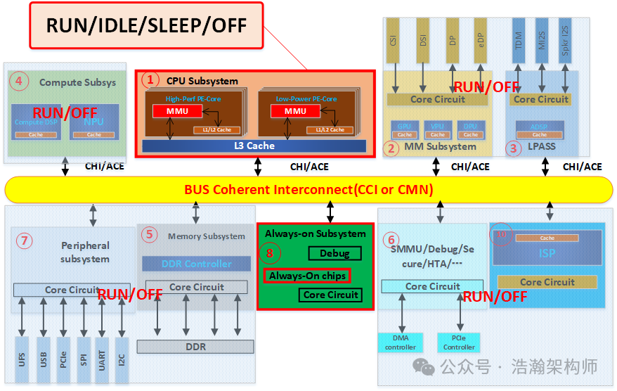
Figure 1-1 Example of SOC Power States
1.1.1 Challenges
With a global view of the SoC, we now focus on the CPU subsystem. As previously discussed, OSPM manages CPU power through two main approaches: IDLE management and DVFS management. Today, we will examine the first approach, IDLE management:
Idle management is typically under the control of the operating system. In this case, when a core is idle, Operating System Power Management (OSPM) moves it into a low-power state. Typically, a choice of states is available, with different entry and exit latencies, and different levels of power consumption associated with each state. The state that is used typically depends on how quickly the core is required again. The power states that can be used at any one time might also depend on the activity of other components in a SoC, besides the cores. Each state is defined by the set of components that are clock-gated or power-gated when the state is entered.
A challenge for idle power management is that various operating systems, from various vendors, can be simultaneously executing in an Arm system. It is then necessary to have a method of collaboratively performing power control. For example, if the operating system that is managing power, running at one level of privilege, wants to enter a state that powers on or off a core, then operating systems at other levels of privilege need to react to this request. Equally, if a core is woken from a power state by a wake-up event, it might be necessary for operating systems running at different levels of privilege to perform actions, such as restoring state. The Power State Coordination Interface (PSCI) specification provides an interface for this purpose.
PSCI leads to a power state change request to an SCP software interface. The SCP firmware acts on that message and manages all hardware level details.
We summarize the description from the manual as follows:
(1) Managing the power state of a power domain through OSPM is a complex task, primarily reflected in three points:
• One is that interacting with the SCP is very cumbersome, involving a large number of IO operations. Communication between the CPU and other IPs on the bus is quite troublesome, making programming difficult and error-prone, which is even more pronounced for such a sensitive subsystem as power.
• For the CPU subsystem, there are many internal power domains, and each power domain corresponds to multiple power modes and states, increasing the complexity of managing the power state machine.
• The power domains within the CPU and the SoC have an inheritance relationship, which further exacerbates the difficulty of OSPM managing the power states of various power domains within the CPU.
(2) From an integration perspective, due to the presence of different operating systems and various chip OEM manufacturers in the market, all must adapt to ARM architecture-based SoC systems. If each acts independently, it will not only increase the cost of the SoC but also present numerous stability issues that need to be overcome.
(3) With the continuous upgrade of the ARM architecture, the software architecture based on the ARM system is becoming increasingly complex. Especially with the introduction of virtualization and security mechanisms, particularly the RME mechanism, the software system itself has also become more complex, as shown in Figure 1-2. Imagine that an EL1 OS wants to put a PE-Core into an idle state; due to its limited privileges, the software system must have a module that considers the feelings of the hypervisor running on this PE-Core and the TEE-OS and APP in the security world.
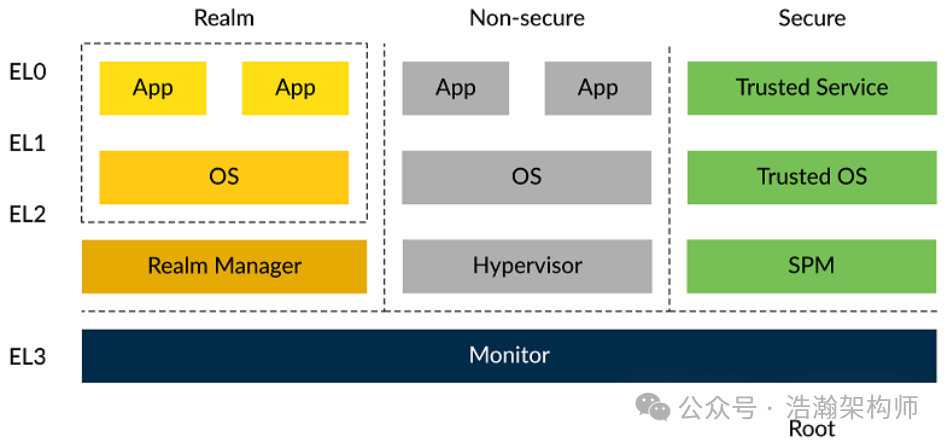
Figure 1-2 Realm Management Extension
1.1.2 PSCI (Power State Coordination Interface)
In light of the challenges posed by power management mentioned earlier, ARM has proposed a solution: PSCI:
This PSCI is for PE and system-level power management that can be used by OS vendors for supervisory software working at different levels of privilege on an Arm device.
Rich operating systems like Linux and Windows, hypervisors, privileged firmware, and Trusted OS implementations must interoperate when power is being managed. The aim of this standard is to ease the integration between supervisory software from different vendors working at different privilege levels.
This interface standard is aimed at the generalization of code in the following power management scenarios:
• Core idle management.
• Dynamic addition and removal of cores, and secondary core boot.
• System shutdown and reset.
The interface does not cover Dynamic Voltage and Frequency Scaling (DVFS) or device power management (for example, management of peripherals such as GPUs). Arm recommends using Advanced Configuration and Power Interface, or System Control and Management Interface as the standard interface for such features.
The interface is designed so that it can work in conjunction with hardware discovery technologies such as Advanced Configuration and Power Interface (ACPI) and Flattened Device Tree (FDT). It is not a replacement for ACPI or FDT.
We summarize ARM’s problem-solving approach:
(1) Abstract a set of interfaces, PSCI, for software developers at all levels, noting that it is for developers at all levels (EL1/EL2/EL3), specifying their respective responsibilities. By implementing the interface, everyone can complete the power state management work for ARM-based systems.
(2) This set of interfaces covers three scenarios: IDLE management of PE-Cores, hot-plugging of PE-Cores, and system shutdown and reset. (Once you have completed mass production projects, you will find that these are common areas for system crashes and black screens.)
(3) PSCI can be integrated with other interface standards (such as ACPI) rather than replacing them, as shown in Figure 1-3. (This part will not be elaborated on here; a dedicated article will be planned for discussion later.)
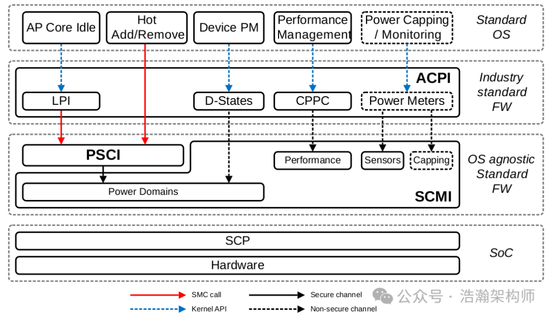
Figure 1-3 Infrastructure system: example power management software stack
1.2 PSCI Software Architecture
1.2.1 Exception Model
Before explaining the PSCI architecture, it is necessary to clarify a concept: the ARM exception model. As shown in Figure 1-4:
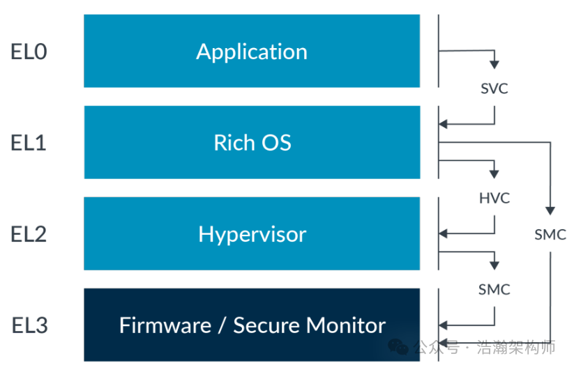
Figure 1-4 Service call routing
Let’s look at the description in the manual:
The name for privilege in AArch64 is Exception level, often abbreviated to EL. The Exception levels are numbered, normally abbreviated and referred to as EL(x), where (x) is a number between 0 and 3. The higher the level of privilege, the higher the number. For example, the lowest level of privilege is referred to as EL0.
The architecture does not specify what software uses which Exception level. A common usage model is application code running at EL0, with a rich Operating System (OS) such as Linux running at EL1. EL2 may be used by a hypervisor, with EL3 used by firmware and security gateway code.
For example, Linux can call firmware functions at EL3, using software interface standards, to abstract the intent from the lower-level details for powering on or off a core. This model means the bulk of PE processing typically occurs at EL0/1.
The Arm architecture includes the exception-generating instructions SVC, HVC, and SMC. The purpose of these instructions is solely to generate an exception and enable the PE to move between Exception levels:
• The Supervisor Call (SVC) instruction enables a user program at EL0 to request an OS service at EL1.
• The Hypervisor Call (HVC) instruction, available if the Virtualization Extensions are implemented, enables the OS to request hypervisor services at EL2.
• The Secure Monitor Call (SMC) instruction, available if the Security Extensions are implemented, enables the Normal world to request Secure world services from firmware at EL3.
When the PE is executing at EL0, it cannot call directly to a hypervisor at EL2 or secure monitor at EL3, as this is only possible from EL1 and higher. The application at EL0 must use an SVC call to the kernel, and have the kernel perform the action to call into higher Exception levels.
After the ARM architecture upgraded to V8, the exception model was introduced, dividing the CPU’s runtime privileges into four levels, increasing sequentially. Typically, the CPU operates at EL0/1, and when higher privileges are needed, it will request higher privilege services through passive traps or active instructions (SVC/HVC/SMC). It is important to note that if the EL2 virtualization layer is implemented, then even if EL1 calls the SMC instruction, it cannot directly request services from EL3.
We have previously analyzed the ARM exception model in a dedicated article, so we will not elaborate on it here. We recommend that readers review the earlier article.
1.2.2 PSCI Architecture (Software Architecture for Power State Management)
With the previous foundation, let’s look at the software architecture for power state management, as shown in Figure 1-5:
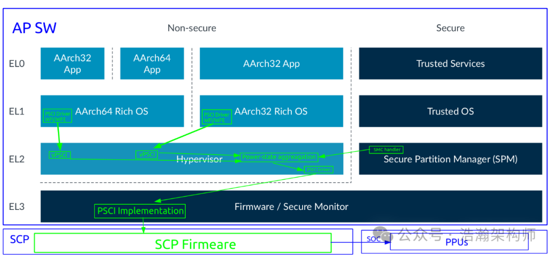
Figure 1-5 High-Level PSCI Software Architecture
Note that this is just an example of a PSCI implementation; the specific design and implementation depend on the software code of the SoC you receive. Below, we will discuss the PSCI software architecture based on the above:
The PSCI interface must support interaction at all levels of execution implemented on the device, where multiple levels of supervisory software might be executing. For the caller operating in the Normal world, the interface must forward a message to the PPF. In a system that implements EL2, it must be possible to trap interface calls made by the EL1 kernel context to the hypervisor (EL2). In a system that implements Arm RME, it must be possible to trap interface calls made by the Realm executing at R-EL1, to the RMM executing at R-EL2. The RMM can then decide to forward the call to the Hypervisor executing at NS-EL2. If the hypervisor determines that a change of physical power state is required, it must then be able to use the PSCI interface to inform the PPF.
The conduits available to transfer a message from one Exception level to another depend on the implemented Exception levels and Security states.
Arm systems generally include a power controller, or control logic, that can manage core power. This normally provides interfaces that support several power management functions. Often these include support for transitioning cores, clusters, or a superset into low-power states. In the low-power state, the cores are either fully switched off or in quiescent states where they are not executing code. Arm strongly recommends that the EL3 is responsible for the control of these states. Otherwise, cleanup of the Root and Secure state, including cache clean, is not possible prior to entering the low-power state. Other forms of power management, such as dynamic performance management through voltage and frequency scaling, are not covered by this interface. Arm strongly recommends that all policy in power and performance management is performed in the Normal world. The Normal world has greater visibility of the current use and purpose of a given device. Where the Secure world has performance requirements, Arm recommends that IMPLEMENTATION DEFINED mechanisms are used to communicate those requirements to the Normal world.
Combining the manual’s description, we summarize as follows:
(1) Except for EL0, each level must implement the PSCI interface adaptation. However, this does not mean that every time direct communication with the SCP is possible. ARM recommends that direct communication with the SCP be implemented within EL3. This is relatively easy to understand; lower privilege ELx software must request power resources from higher privilege ELx layers, while the reverse is not possible. This naturally divides the entire PSCI interface adaptation into two parts: one part located at EL1 or EL2. EL1 primarily considers how to migrate power states from its own VM perspective (vCPU: virtual CPU), while EL2 must consider how to migrate power states from the perspective of all VMs (pCPU: physical CPU). The firmware within EL3 must implement the state coordination that PSCI carries and complete communication with the SCP.
(2) With the introduction of virtualization technology, the implementation of OSPM is divided into two layers: EL1 and EL2. Depending on the type of virtualization, the specific implementation varies, as shown in Figure 1-6:
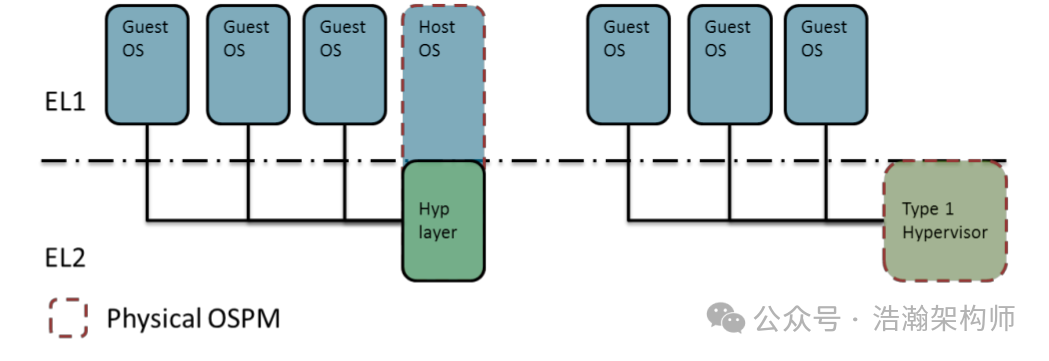
Figure 1-6 Typical Power Management Models in Virtualization
Let’s look at the description in the manual:
Physical OSPM: This comprises the software components that select the physical power states.
Virtual OSPM: This is an OSPM that is present in a guest OS running a virtual machine, which selects virtual, rather than physical power states.
This part matches closely with the software modules described in (1) and the software architecture diagram, so we will not elaborate further.
(3) With the introduction of Secure implementations, the PSCI software architecture can be further abstracted, as shown in Figure 1-7:
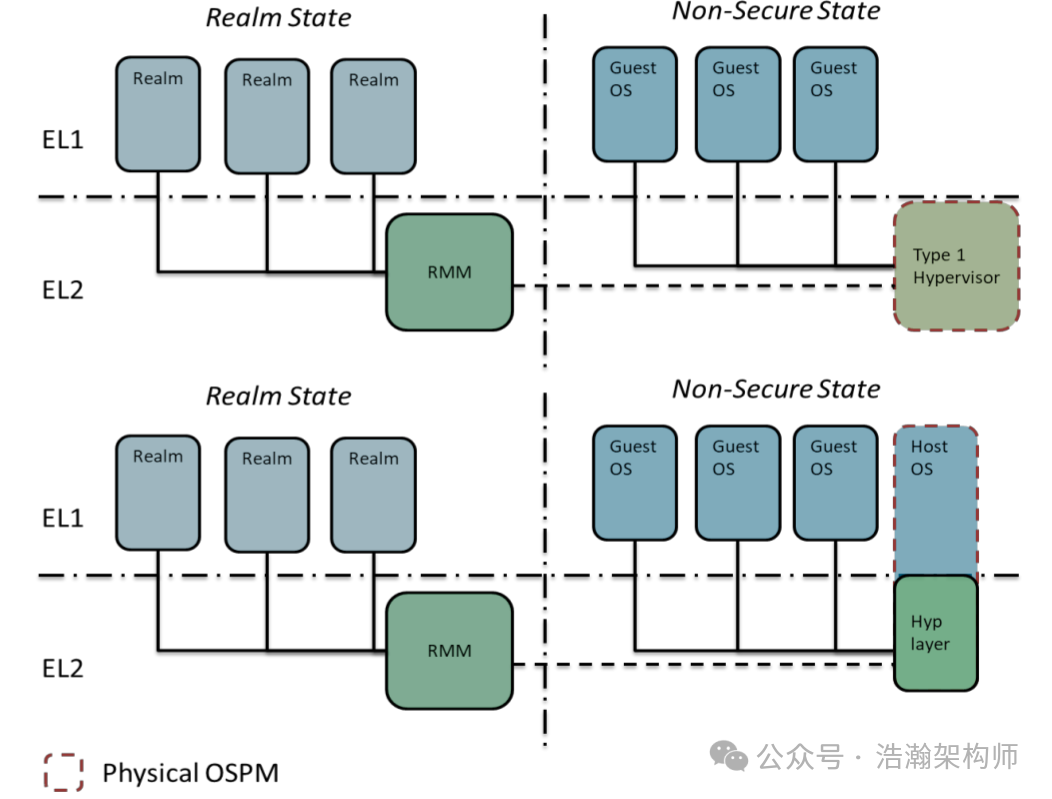
Figure 1-7 Typical Power Management Models with Arm RME
Let’s look at the description in the manual:
Many Trusted OS implementations are not SMP-capable. When running on MP devices, they are tied to a single core. Secure Monitor Calls destined for the Trusted OS are only expected to come from that core. The lack of MP support in the OS helps to keep Trusted code simple and small, which in turn aids certification. Trusted OS services are invoked from the Normal world through Rich OS drivers or daemons that are provided with the Trusted OS implementations. The threads associated with these drivers and daemons are normally affinitized to the core used by the Trusted OS.
When Arm RME is implemented, and the Realm Security state is present, Realms access PSCI services through the RMM. The RMM coordinates with the Hypervisor in Non-secure EL2 irrespective of the Hypervisor type. The decision for physical power management is made in the same manner as in a system without Realms.
We will discuss this from two perspectives:
• The Secure world is primarily for granting trust to RichOS, so the implementation aims to be efficient and simple. In power management, ARM does not want TrustZone to participate too much, meaning that the power management tasks of the non-secure world should not be coupled with the secure world. The secure world should only focus on trust-related tasks.
• Therefore, the power state management tasks of the secure world cannot be self-contained. ARM hopes that they will aggregate power state requests to the Hypervisor for comprehensive decision-making, which will then be sent to the SCP through the firmware program in EL3.
1.2.3 PSCI Architecture in Linux
Let’s look at the PSCI architecture in Linux, as shown in Figure 1-8:
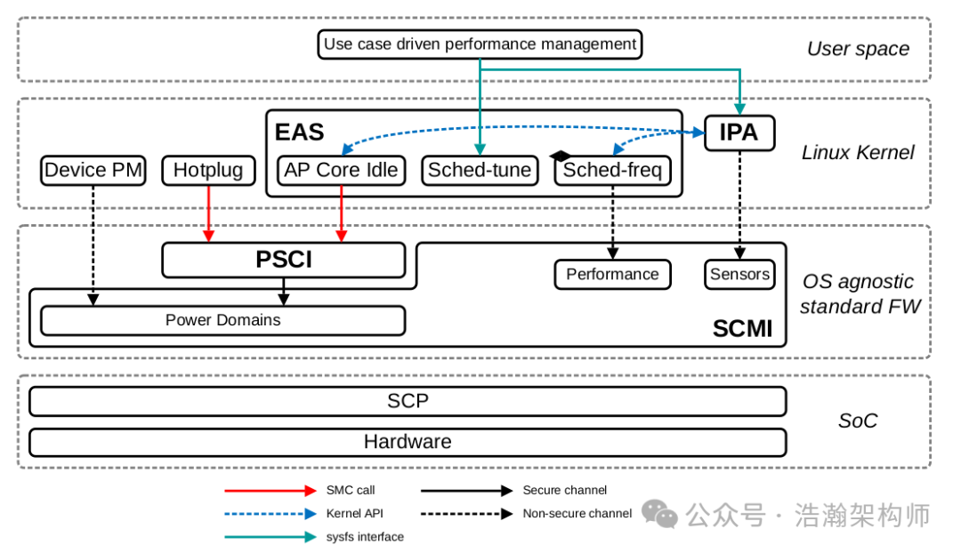
Figure 1-8 Linux Mobile: Example Power Management Software Stack
Let’s look at the description in the manual:
In the Linux kernel, Energy Aware Scheduling (EAS) provides the core scheduling with tight links to core idle and integrated frequency control. EAS is also linked to a thermal management solution using Intelligent Power Allocation (IPA). Finally, both EAS and IPA have linkages to user space performance management interfaces.
An OS agnostic firmware layer includes an implementation of PSCI as outlined in Idle Management. SCMI provides an interface for communication with the SCP firmware. It supports protocols for power and performance control in addition to sensors, such as those for temperature measurements, used by IPA.
The reason for mentioning this part is that we will later introduce some details about it in subsequent articles, such as the EAS algorithm that affects system scheduling. In fact, one reason we initially wrote about power management was to address system optimization involving the EAS algorithm. Returning to the implementation of PSCI within the Linux system, we first need to focus on cpu_operations, as shown in Figure 1-9:
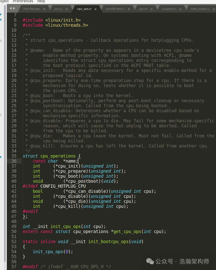
Figure 1-9 cpu_operations struct
cpu_operations is the gateway for the Linux system to control the CPU through the ARM world. Behind this gateway lies the details of PSCI to EL3, as shown in Figures 1-10, 1-11, and 1-12:
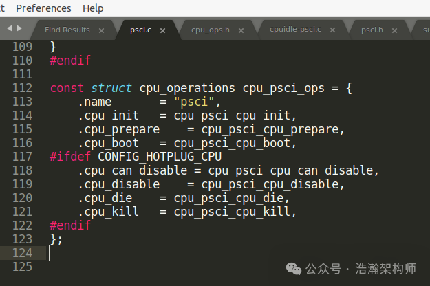
Figure 1-10 cpu_operations Assignment
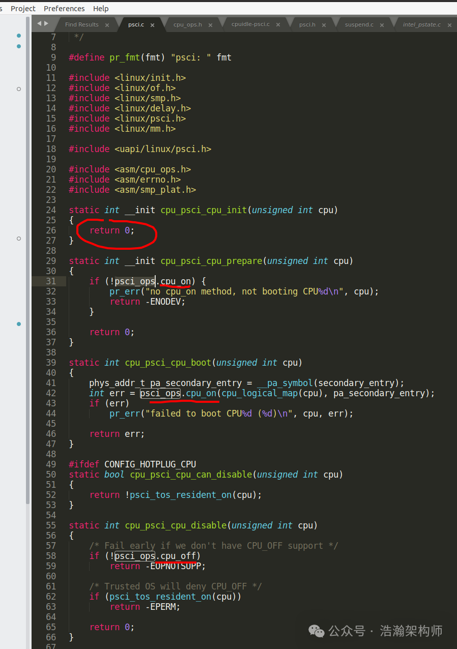
Figure 1-11 cpu_operations Assignment Call
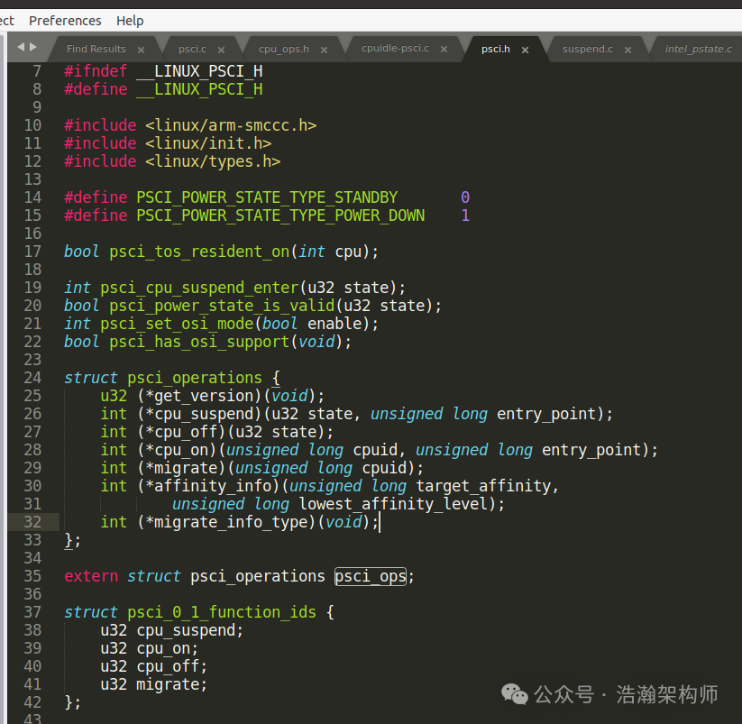
Figure 1-12 psci_operations
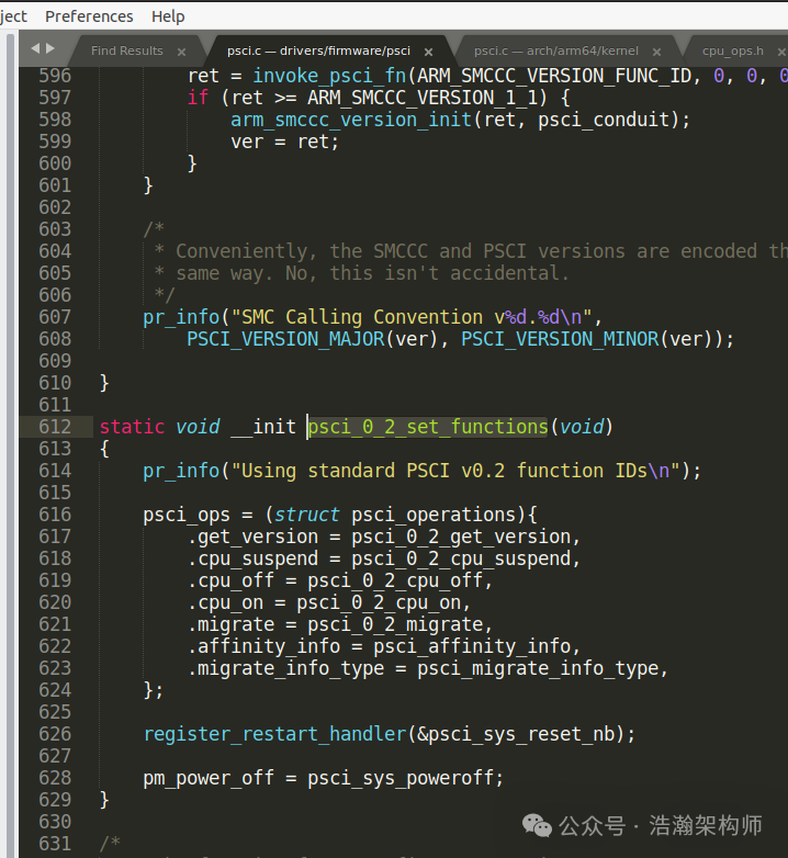
Figure 1-13 psci_operations Assignment
Here are some key codes listed; interested readers can read the code themselves, and we will not elaborate further. It should be noted that this is not the end; the endpoint is the SMC call. It is important to clarify that under the virtualization architecture, this set of code does not need to change. The reason is that we mentioned earlier that SMC cannot cross the EL2 domain; the SMC instruction executed by EL1 will trap into the Hypervisor for processing.
Conclusion
This article discussed the PSCI architecture, starting from the challenges of OSPM in power state management, leading to ARM’s proposed solution, the PSCI interface. Rather than merely an interface, it is more accurately described as a mechanism that spans from EL1 to EL3, with different responsibilities at each layer. The power states within each VM are essentially virtualized states; even the power states of the secure world are not the final physical CPU power states. Ultimately, they are all aggregated through the power service at the EL2 level for comprehensive decision-making, which is then sent to the firmware in EL3 and forwarded to the SCP, which then switches the physical CPU’s power mode. At the end of the article, we listed the PSCI architecture in Linux and some code snippets to help readers establish a preliminary understanding of the PSCI interface. In the next article, we will provide a detailed introduction to the business involved with the PSCI interface. That’s all for today; thank you for your attention, shares, and comments.
Reference
[01] <DEN0050D_Power_Control_System_Architecture.pdf>
[02] <armv8_a_power_management_100960_0100_en.pdf>
[03] <Power_Policy_Unit_Architecture_Specification_V_1_1_ARM_DEN_0051E.pdf>
[04] <DEN0024A_v8_architecture_PG.pdf>
[05] <79-LX-LD-s003-Linux设备驱动开发详解4_0内核-3rd.pdf>
[06] <80-PGxxx-35_QNX_Thermal_Manager_Overview.pdf>
[07] <80-pgxxx-7_n_qnx_power_management_software_architecture_reference_manual.pdf>
[08] <80-ARM-POWER-HK0001_一文搞懂ARM_SoC功耗控制架构.pdf>
[09] <Arm_Power_and_Performance_Management_SCMI_White_Paper.pdf>
[10] <80-ARM-POWER-cs0001_Arm-SoC-power功耗控制架构.pdf>
[11] <80-LX-LK-cl0009_深入理解Linux电源管理.pdf>
[12] <DEN0056D_System_Control_and_Management_Interface_v3_1.pdf>
[13] <arm_total_compute_2021_reference_design_software_developer_guide_en.pdf>
[14] <arm_total_compute_2022_reference_design_software_developer_guide_en.pdf>
[15] <arm_cortex_m85_processor_trm_en.pdf>
[16] <DEN0108_00eac0_smcf-archl-Specification.pdf>
[17] <DEN0022F.b_Power_State_Coordination_Interface.pdf>
[18] <MTxxxx_SCP_User_Manual_V1.0.pdf>
[19] <learn_the_architecture_arm_system_architectures_en.pdf>
[20] <arm_dsu_110_trm_101381_0400_11_en.pdf>
[21] <DEN0077A_Firmware_Framework_Arm_A_profile_1.1_EAC0.pdf>
[22] <80-LX-POWER-PSCI-cs0001_Linux-PSCI框架.pdf>
[23] <learn_the_architecture_-_realm_management_extension_guide.pdf>
Glossary
AP – application processor
OSPM – Operating System Power Management
WFI – Wait For Interrupt
WFE – Wait For Event
DVFS – Dynamic Voltage and Frequency Scaling
SCU – Snoop Control Unit
OPP – Operating Performance Point
PSCI – Power State Coordination Interface
PPU – Power Policy Unit
PCSA – Power Control System Architecture
SoC – System-on-Chip
PCF – Power Control Framework
SCP – System Control Processor
BSP – board support package
SCMI – System Control and Management Interface
EAS – Energy Aware Scheduling
IPA – Intelligent Power Allocation
ACPI – Advanced Configuration and Power Interface
LPI – Low-Power Idle
CPPC – Collaborative Processor Performance Control
PCSM – power control state machine
AOSS – Always-on subsystem
PMIC – Power Management Integrated Circuit
JM – job manager
AON – always on domain
SBSA – Server Base System Architecture
CLK_CTRL – Clock Controller
LPD – Low Power Distributor
LPC – Low Power Combiner
P2Q – P-Channel to Q-Channel Convertor
GPIO – General Purpose IO
RAS – Reliability, Availability, and Serviceability
STR – Suspend to RAM
SMCCC – SMC Calling Convention
RMM – Realm Management Monitor
BMC – board management controller
PPF – Privileged platform firmware