ver0.1
Introduction
In previous articles, we invested significant effort in introducing the hardware and software architecture of the ARM interrupt subsystem, laying the foundation for our further research into virtualization technology. Today, we will discuss a topic that requires a basic understanding of the interrupt subsystem. To fully grasp it, we recommend that everyone read the relevant materials. The system we will discuss is the Timer subsystem of a SoC. Understanding the working principle of the Timer will clarify the operational basis of the core scheduling subsystem of the software operating system. Therefore, before delving into the scheduling mechanism, let’s take some time to study the Timer. The names of timers vary across different chip architectures; in the ARM architecture, it is referred to as the Generic Timer. (It is important to note that the system architecture of the Timer varies among different ARM CPU IPs, and the implementation of the Timer differs across various CPUs. For example, the descriptions of Timer implementations in the MTK chips 8676/8678 and Qualcomm 8155/8295 manuals show significant differences, with Qualcomm’s implementation being notably more complex.)
(1) [V-00] Introduction to Virtualization – Conceptual Part
(2) ARM Interrupt Subsystem
(3) [V-02] Basics of Virtualization – CPU Architecture (Based on AArch64)
(4) [V-05] Basics of Virtualization – Exception Model (AArch64)
Main Text
1.1 Background
In this section, we will discuss the Timer from two aspects: SoC and resource scheduling.
1.1.1 SoC and Timer
For those who have read the previous article on “CPU Architecture,” you should be familiar with what an SoC is. Chip companies that cannot produce good SoCs are embarrassed to engage with others: with the same battery capacity, one company’s phone can play games for 8 hours, while yours drains power quickly just watching videos; with the same applications, one phone runs smoothly like chocolate and doesn’t overheat, while yours becomes a hot potato after a short while. This disparity arises from differences in SoC hardware processes and the level of software optimization for system performance and thermal management. Therefore, when choosing electronic products, be discerning.
Chip companies connect multiple IPs in parallel through a bus, and to coordinate their operation, they must agree on strategies in advance. For example, the GIC and PE-Core must agree that after five pulse signals, an interrupt signal will be sent, so be prepared. When a heavy computational task is scheduled on a PE-Core, the current PE-Core frequency must be increased to execute more instructions in the same unit of time. Similarly, other IPs on the bus, such as GPU, APU, ADSP, etc., must also agree with the bus in advance. IPs that support dynamic frequency scaling must have mechanisms to ensure they operate at relatively reasonable power consumption levels to avoid overheating the SoC and affecting user experience. Just like in our society, to ensure that this small “community” of the SoC operates efficiently and in sync, good time management is essential. If work starts at 9 AM, it must start at 9 AM; if a bus departs at 7 AM, it must leave at 7 AM. Everyone must be a master of time management. So, see Figure 1-1:
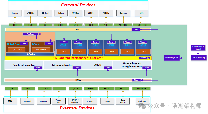
Figure 1-1 General SoC Timer Subsystem Model
The above model is summarized from several production chip manuals. Due to copyright considerations, the original images cannot be posted, and all architectures above are for reference only. Generally, a Timer subsystem consists of three parts: a clock source (crystal oscillator); frequency division/multiplication circuits (PLLs); and internal clock circuits of the IP. These three parts are connected through an on-chip clock bus to form a tree-like structure known as a clock tree. The clock source is the root, the PLLs subsystem is the trunk, and the internal clock circuits of each IP are the leaves, while the clock bus serves as the branches. The working principle is roughly that the clock source inputs a fixed frequency pulse signal into the SOC’s internal PLLs, which then divide or multiply these clock signals according to current operational requirements (different CPU clusters operate at different frequencies) and inject them into the clock circuits of various modules within the SOC via the clock bus. The internal clock circuits of each IP take over these signals to coordinate the operation of other circuit logic within the IP based on these signals. For example, increasing the frequency of a specific PE-Core allows it to operate in Performance mode, or continuously feeding the watchdog proves that the current SOC is functioning normally, etc. To delve deeper into this part requires a foundation in digital electronics and bus architecture, which we will not discuss here. In summary, everyone should know where the clock signals come from and where they go.
1.1.2 Time Slices
When we discussed the concept of virtualization earlier, we explained that the operating system abstracts and isolates hardware resources on the SoC to achieve time-sharing reuse, allowing various processes within the system to utilize them. The core idea of virtualization is to abstract and isolate hardware resources on the SoC to achieve time-sharing reuse for various VMs running on the Hypervisor. Whether it is a single system OS (like Linux) or a virtualization core Hypervisor (like KVM), their core module is the Scheduler module, which distributes system resources to various modules within the software system according to certain strategies. Taking real-time operating systems as an example:
A real-time system is one in which the correctness of the computations not only depends upon the logical correctness of the computation but also upon the time at which the result is produced. If the timing constraints of the system are not met, system failure is said to have occurred.
Hard real-time is a property of the timeliness of a computation in the system. A hard real-time constraint in the system is one for which there’s no value to a computation if it’s late, and the effects of a late computation may be catastrophic to the system. Simply put, a hard real-time system is one where all of the activities must be completed on time.
Soft real-time is a property of the timeliness of a computation where the value diminishes according to its tardiness. A soft real-time system can tolerate some late answers to soft real-time computations, as long as the value hasn’t diminished to zero. A soft real-time system often carries meta requirements, such as a stochastic model of acceptable frequency of late computations. Note that this is very different from conventional applications of the term, which don’t account for how late a computation is completed or how frequently this may occur.
The above definitions of real-time systems, hard real-time, and soft real-time are summarized from QNX’s official documentation. In summary, real-time operating systems are highly sensitive to time, with hard real-time requiring tasks to be completed within specified time limits, while soft real-time can relax some of the constraints of hard real-time.
Using the QNX system as an example, let’s look at the scheduling strategy for resource allocation in the system. We use QNX as an example because its scheduling strategy is purely based on time slices as the metric for resource usage. Higher-priority threads can preferentially obtain PE-Core resources until execution is complete, as shown in Figure 1-2:
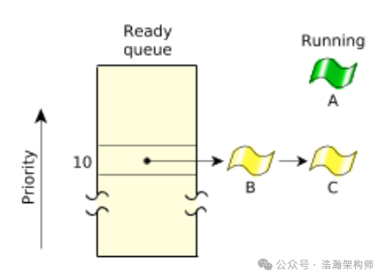
Figure 1-2 FIFO Scheduling
When there are multiple threads with the same priority, the time slice is equally divided among the threads of the same priority. When the time slice is exhausted, the PE-Core is yielded to the next ready thread for execution, as shown in Figure 1-3:
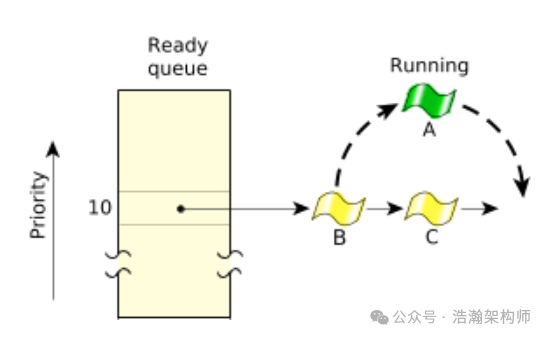
Figure 1-3 Round-robin Scheduling
Here, the concept of time slices emerges:
A timeslice is the unit of time assigned to every process. Once it consumes its timeslice, a thread is preempted and the next READY thread at the same priority level is given control.
Of course, QNX has even more refined scheduling strategies, as shown in Figure 1-4:
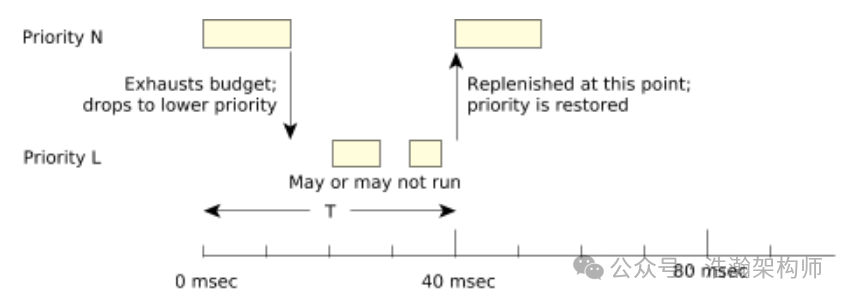
Figure 1-4 Sporadic Scheduling
Sporadic scheduling can further promote fairness in resource allocation through periodic compensation measures. The above is QNX’s scheduling strategy for general threads. Resource allocation at the virtualization layer in QNX is also based on time slices, as shown in Figure 1-5:
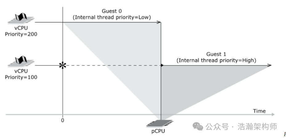
Figure 1-5 vCPU Scheduling
In addition to vCPU priority, QNX also provides an APS mechanism that can influence the allocation of PE-Core resources within the system. Regardless of how PE-Core resources are allocated, the only unit for measuring resources is the time slice. To ensure good system performance, resources must be allocated clearly in terms of time.
Of course, time slices are important not only for real-time operating systems like QNX but also for time-sharing operating systems like Linux. However, the scheduling system in Linux is more complex, so we used the QNX system as an example to provide a basic understanding of time slices.
1.2 Generic Timer System Architecture
With the background information provided above, I believe everyone should have a basic understanding of the Timer and its role in the system, especially for developers who should have sufficient knowledge to carry out deeper optimization work. In this section, we will focus on the CPU’s internal architecture of the Generic Timer in the ARM architecture, as shown in Figure 1-6:
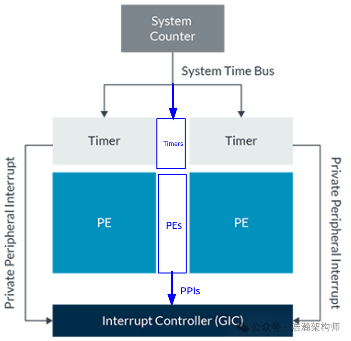
Figure 1-6 High-Level Generic Timer Architecture
Let’s look at the description in the manual:
The System Counter is an always-on device, which provides a fixed frequency incrementing system count. The system count value is broadcast to all the cores in the system, giving the cores a common view of the passage of time. The system count value is between 56 bits and 64 bits in width, with a frequency typically in the range of 1MHz to 50MHz.
Each core has a set of timers. These timers are comparators, which compare against the broadcast system count that is provided by the System Counter. Software can configure timers to generate interrupts or events at set points in the future. Software can also use the system count to add timestamps, because the system count provides a common reference point for all cores.
It is important to clarify that this article does not cover RTC-related content. Although we have depicted the RTC chip in Figure 1-1, our clock signals also come from this chip, but the RTC in a system is essentially a real clock, just like the watch on your wrist, which can be implemented inside or outside the SoC depending on the working scenario and the chip manufacturer’s preferences. This article only discusses the Timer subsystem within the CPU. Under this premise, we summarize the manual’s description as follows:
(1) The System Counter is a timer that records the elapsed time and synchronizes this count information equally to all PE-Cores.
(2) The Timer acts like an alarm clock, where software can control the alarm to trigger interrupts or events for the PE-Core.
(3) The Timer is associated with the PE-Core and consists of a set, not just one.
(4) The Generic Timer is only used to record time counts and trigger related interrupts to notify the PE-Core; it is not directly related to the frequency control of the PE-Core’s operation. There is another set of frequency controllers within the CPU that control the operational state of the PE-Core, which is another topic that we will explore in future articles when discussing thermal management. Here, please do not confuse the two.
1.2.1 System Architecture of the Generic Timer
This section will introduce the Generic Timer within the PE-Core, as shown in Figure 1-7:
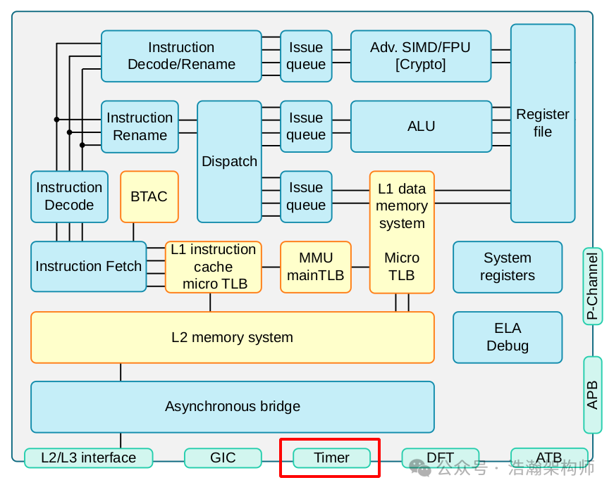
Figure 1-7 High-Level Cortex‑A75 Core Overview
Let’s look at the manual’s introduction to the A75 Timer:
The Generic Timer can schedule events and trigger interrupts based on an incrementing counter value. It generates timer events as active-LOW interrupt outputs and event streams.
The Cortex‑A75 core provides a set of timer registers. The timers are:
• An EL1 Non-secure physical timer
• An EL2 Hypervisor physical timer
• An EL3 Secure physical timer
• A virtual timer
• A Hypervisor virtual timer
The Cortex-A75 core does not include the system counter. The system counter resides in the SoC, and its value is distributed to the core over a 64-bit bus.
Generic Timers interface supporting 64-bit count input from an external system counter.
Let’s take a look at the earlier Cortex-A57 chip’s Generic Timer, as shown in Figure 1-8:
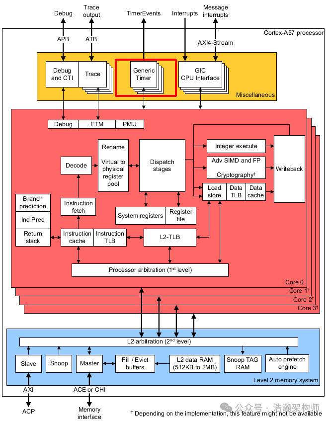
Figure 1-8 High-Level Cortex‑A57 Core Overview
Let’s look at the manual’s introduction to the A57 Timer:
The Generic Timer in the Cortex-A57 processor can schedule events and trigger interrupts based on an incrementing counter value. It provides:
• Generation of timer events as interrupt outputs.
• Generation of event streams.
The Cortex-A57 processor provides a set of timers for each core in the processor. The timers are:
• A Non-secure EL1 physical timer.
• A Secure EL1 physical timer.
• A Non-secure EL2 physical timer.
• A virtual timer.
The processor does not include the system counter that resides in the SoC. The system counter value is distributed to the Cortex-A57 processor with a synchronous binary encoded 64-bit bus.
Let’s look at the manual’s introduction to the A53 Timer:
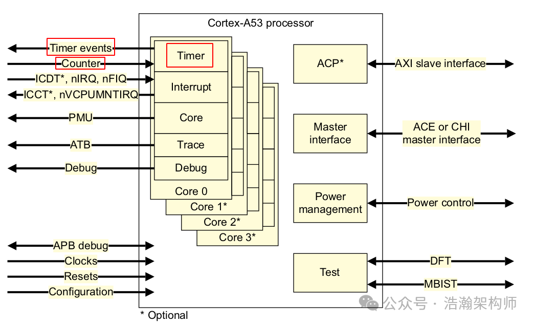
Figure 1-9 High-Level Cortex‑A53 Core Overview
The description of the Timer in the A53 manual is the same as that of the A75 and A57, so we will not include it here. However, the block diagram for the A53 is clearer. Based on the manual’s description, we summarize as follows:
(1) The Generic System Counter comes from outside the CPU, specifically implemented by the SoC chip manufacturer.
(2) Each PE-Core is associated with a set of Timer-related registers.
Finally, let’s look at the support for Timer in ARM’s latest CPU architecture DSU framework, as shown in Figure 1-10:
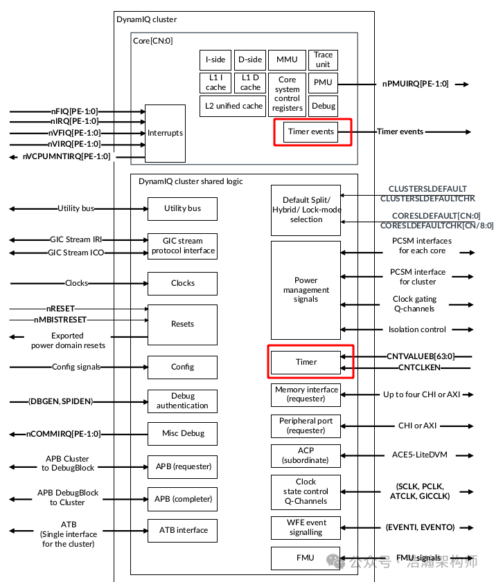
Figure 1-10 High-Level DSU Overview
Let’s look at the description of the timer interface in the DSU manual:
Input for the generic time count value. The count value is distributed to all cores. Each core outputs timer events.
The Cortex-A720 core implements the Arm® v9.2-A architecture. The Arm® v9.2-A architecture extends the architecture defined in the Arm® v8-A architectures up to Arm® v8.7-A. The Cortex-A720 core also implements specific Arm® v8-A architecture extensions and supports interconnect, interrupt, timer, debug, and trace architectures.
The DSU architecture and ARMv9’s mechanism for the Generic Timer are also supported, but we will not elaborate on this part. Interested readers can refer to the manual for further reading.
1.2.2 Generic Timer
In the previous section, we learned that each PE-Core is associated with a set of Timers. We summarize as follows, as shown in Figure 1-11:
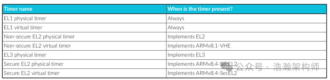
Figure 1-11 The ARM Processor Timers
The above figure clearly shows which specific timers are associated with each PE-Core under the Generic Timer framework, primarily distinguished from three dimensions:
(1) Distinction based on Exception Levels; each privilege level, except EL0, has its own Timer.
(2) Distinction based on security states; both Security and Non-Secure states have their own Timers.
(3) Distinction from the perspective of virtualization; both virtualized and non-virtualized states have their own Timers (this will also be a focus of our future research).
Conclusion
In this article, we introduced the importance of the Timer to a system from the perspective of SoC performance and power consumption, and established an understanding of time slices from the perspective of system resource scheduling. On this basis, we also introduced the system architecture of the ARM Generic Timer, giving us a preliminary understanding of the structure and role of timers in the system. In the next article, we will discuss the working principles of Timers and their roles in virtualization architecture. Thank you all for your attention, likes, and shares. (I have been very busy lately and haven’t had enough time to conduct research and write articles. Fortunately, I have been working on scheduling optimizations, and the Timer is also a foundational subsystem for future research, hence this article.)
References
[00]<80-Virt-ARCN-T-I0001_Timer.pdf>
[01]<80-Virt-ARCN-T-I0002_System-Timer-Virtualization.pdf>
[02]<learn_the_architecture_generic_timer_en.pdf>
[03]<80-LX-T-wx0001_从硬件到软件-Linux时间子系统全栈解析.pdf>
[04]<79-LX-LD-yk-Linux-Driver-Foundation.pdf>
[05]<79-LX-LK-LKD-ch-3rd.pdf>
[06]<79-LX-LD-s003-Linux设备驱动开发详解4_0内核-3rd.pdf>
[07]<80-LX-LK-cl0010_深入理解Linux时间子系统.pdf>
[08]<arm_cortex_a75_core_trm_100403_0301_01_en.pdf>
[09]<arm_cortex_a720_core_trm_102530_0001_04_en.pdf>
[10]<arm-dsu-120_trm_102547_0201_07_en.pdf>
[11]<DDI0500J_cortex_a53_trm.pdf>
[12]<SysReg_xml_A_profile-2024-03.pdf>
Glossary
SoC – System on a Chip
DVFS – Dynamic Voltage Frequency Scaling
LDO – Low Dropout Regulator
OPP – Operating Performance Point
MLME – MAC sublayer management entity
PLME – PHY sublayer management entity
DSAP – Destination Service Access Point
SSAP – Source Service Access Point
vDSO – virtual dynamic shared object
NTP – Network Time Protocol
jiffies – a moment; instant
SBSA – Server Base System Architecture
GIC – Generic Interrupt Controller
PPI – Private Peripheral Interrupt
WDT – watchdog timer
PLL – Phase-Locked Loop