Arduino Lesson 6: Digital Signals
Rubin said April 21, 2025 11:56 Qinghai

 01Analog Signals
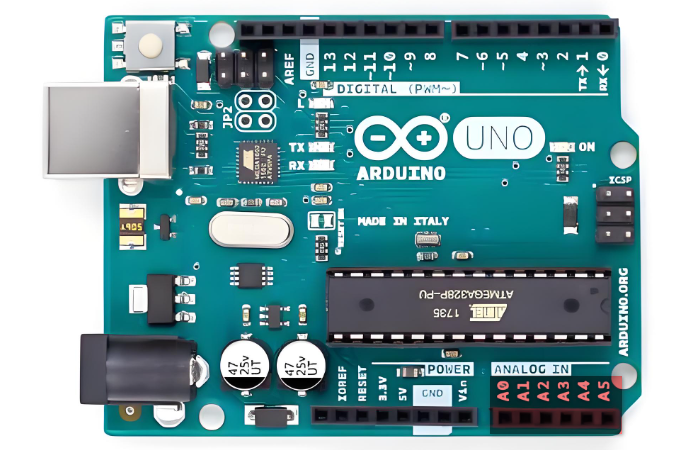 Analog signals: are information expressed by continuously varying physical quantities, also known as continuous signals that have multiple different values within a certain time range.During the transmission process, the information signal is first converted into an electrical signal (hence called “analog”), and then transmitted. After receiving the electrical signal, the receiving device restores it back to the information signal. In the Arduino controller, the pins numbered with an “A” are analog input pins (A0-A5: marked in red in the above image), which can detect voltage signals from 0-5V, converted into integer values from 0-1023 through a 10-bit ADC (Analog-to-Digital Converter).Advantages:1. Precise resolution; 2. Compared to digital signals, analog signals have higher information density; 3. Information processing is simpler ( due to the absence of quantization errors, it can describe the true values of physical quantities in nature as closely as possible).Disadvantages: Always affected by noise (random variations in the signal that are undesirable).02Notes Analog inputs are in a high-impedance state, suitable for detecting weak signals, but should avoid direct connection to high-current devices; Floating pins may cause value fluctuations, and noise should be eliminated through filtering algorithms or hardware design. Use
<span>analogRead(pin)</span> to read the analog signal, with the conversion formula for the returned value: Voltage value (V) = (Read value / 1023) * 5;03Analog Output (PWM)PWM (Pulse Width Modulation) is a powerful technique that is a method of digitally encoding the levels of analog signals;PWM output: Digital pins marked with<span><span>~</span></span> (such as 3, 5, 6, 9, 10, 11), when using the analogWrite(pin, val[0-255]) function, the specified pin will output a fixed-period square wave by continuously switching between high and low levels, achieving the effect of approximating different output voltages by changing the duty cycle within each period.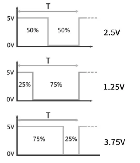 04Code UsageMixly does not require separate pin mode configuration, it automatically recognizes.
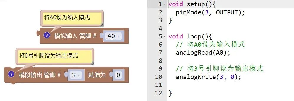

 Share
Share Save
Save View
View Like
Like