Source: Chongqing Yinka Electronics
Yan Bo 136 4836 9639
WeChat ID: yanbo990901
The forest fire sensor network early warning system is an IoT system developed using advanced technologies such as sensing technology, satellite positioning, geographic information, and artificial intelligence. It is suitable for urban forests, nature reserves, tourist attractions, forest parks, and artificially managed bamboo forest areas. It can achieve full digital, full coverage, and all-weather fire monitoring in the monitored area, detecting the location of the fire, spread area, spread speed, spread direction, and development trend, truly realizing forest fire “early, small, and controlled”; This early warning system consists of three parts: fire detection sensor network, fire IoT gateway, and forestry ecological safety emergency command platform system.
The fire detection sensor network is composed of several flame detectors distributed at the forest boundary and within the forest. Each flame detector has flame detection and wireless communication functions, capable of detecting early flames within a range of 100m in no more than 15 seconds, and sending fire situation messages to adjacent detectors via wireless communication, automatically relaying the information in the network until it reaches the fire IoT gateway, which then transmits the fire situation remotely via “GPRS” to the forestry ecological safety emergency command platform, presenting the fire scene in various ways.
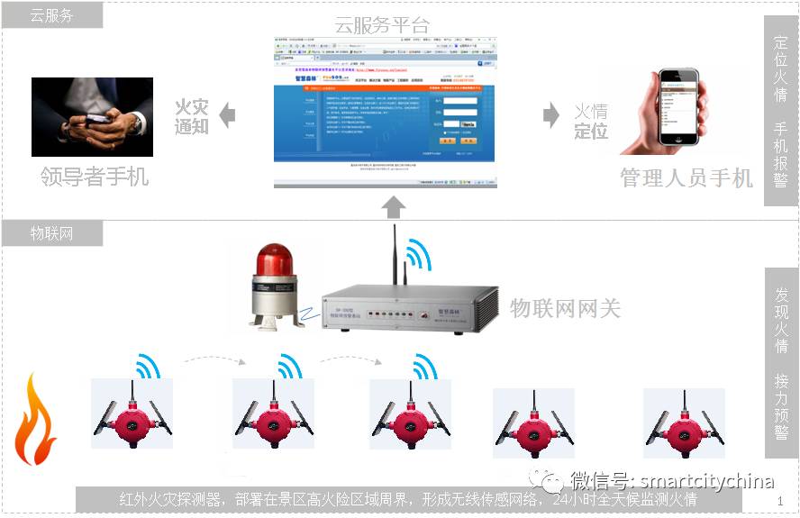
Figure 3.1 System Topology Structure
The spatial deployment of the fire warning system is shown in Figure 3.2:
The workflow diagram of the fire warning system is shown in Figure 3.3: Once a fire occurs in the monitored forest area, the wireless fire detector can detect flames within its detection window in no more than 15 seconds, and send the fire location information to the fire IoT gateway via wireless relay through adjacent detectors, while the IoT gateway issues an audible and visual alarm and simultaneously sends the fire location information to the “GIS” early warning system platform and the backend SMS service platform via “GPRS” and wired network (wired network preferred). The SMS service platform sends out SMS alarms to relevant personnel, and the command management personnel receiving the alarm information can log into the “GIS” early warning system service platform through the nearest internet-accessible computer using the service account provided by our company to view the site map, while also linking video surveillance images and combining with fire prevention plans for command and control of firefighting.
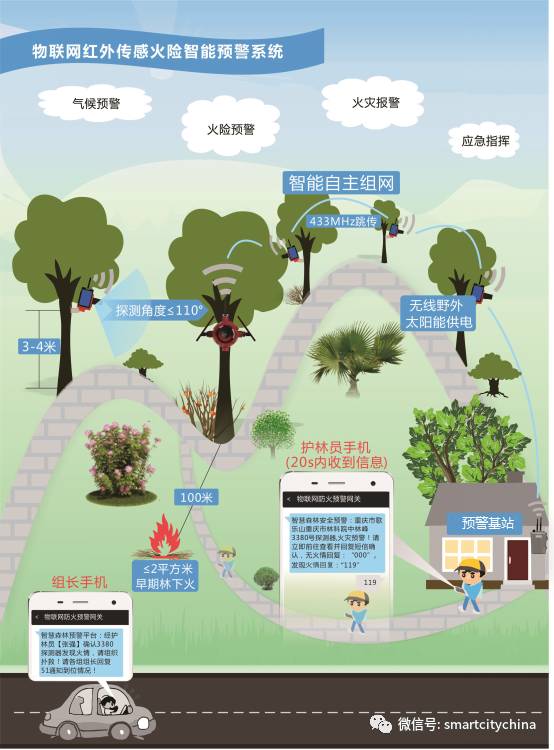
Figure 3.2 System Spatial Deployment Diagram
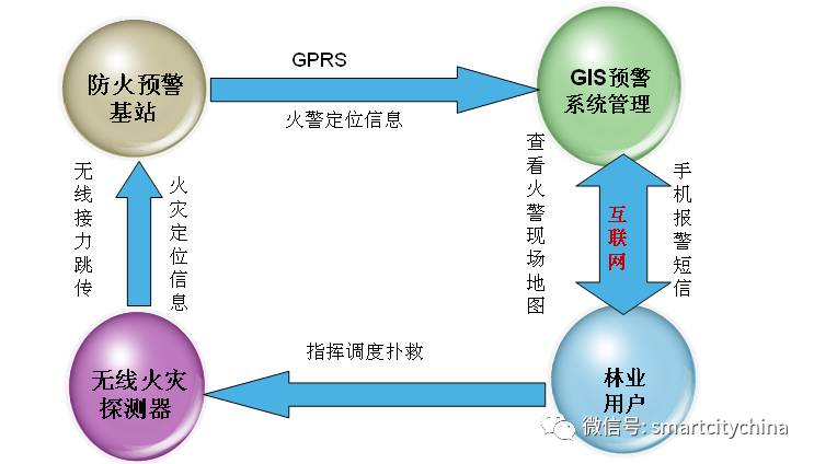
Figure 3.3 System Workflow Diagram
3.2 JTG-HWJ200BN Flame Detector – Product Introduction
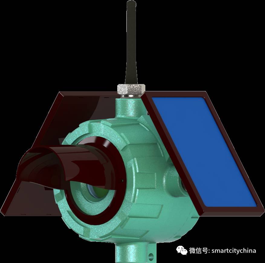
Figure 3.5 JTG-HWJ200BN Flame Detector
The JTG-HWJ200BN flame detector (as shown in Figure 3.5) is an intelligent flame detector that integrates flame detection, temperature detection, wireless communication, self-organizing network, and automatic routing functions. It has significant characteristics such as low power consumption, accurate detection, long transmission distance, and anti-interference, making it suitable for forest fire warning in urban forests, nature reserves, and tourist areas.
n Flame Detection: 50m, can detect flames no larger than 1m2, 100m, can detect flames no larger than 2m2.
n Anti-Interference: Built-in artificial intelligence algorithm can resist sunlight, lightning, and electromagnetic interference;
n Wireless Transmission: RF433MHz wireless communication, communication distance: 800m (depending on the environment);
n Self-organizing Network: The detector automatically forms a sensor network, wirelessly relaying messages;
n Automatic Routing: The detector automatically discovers faulty nodes, re-selects transmission routes, and searches for measurement and control gateways;
n Automatic Anti-theft: The detector has a built-in anti-theft sensor that actively detects and alarms when theft occurs;
n Composite Power Supply: High-energy lithium-ion battery combined with solar panel power supply, average service life of about 5 years;
n Early Warning Function: Fire location, area of ignition, spread speed, spread direction, and trend;
n Early Warning Method: Sends fire location to designated personnel’s mobile phones, presenting fire situation on a three-dimensional “GIS” map;
n Unattended: The IoT gateway initiates a strong audible and visual alarm and simultaneously sends messages to mobile phones, reachable worldwide;
n Shell Protection: IP67, exposure to outdoor sunlight and rain;
n Dimensions: Compact size, easy to install;
3.2.1 Structure Description
The structural diagram of the detector is shown in Figure 3.6, its components are:
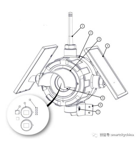
Figure 3.6 Structural Diagram of the Detector
① Antenna; ② Detector Housing; ③ Sunshade; ④ Solar Panel; ⑤ Detection Window;
⑥ Stainless Steel Bracket; ⑦ Bolt; ⑧ Environmental Sensor; ⑨ Infrared Sensor; ⑩ LED Indicator Light
3.2.2 Structural Parameters
The detector housing is made of metal, and its installation diagram is shown in Figure 2.3. The detector bracket is made of stainless steel, and its dimensions are shown in Figure 3.7. The relevant parameters of the detector structure are:
n Dimensions: 245*85*230mm (without sunshade)
n Shell Material: Aluminum Alloy
n Solar Panel: Engineering Plastic
n Installation Bracket: Stainless Steel
n Net Weight: 1.2Kg
n Protection Level: IP67
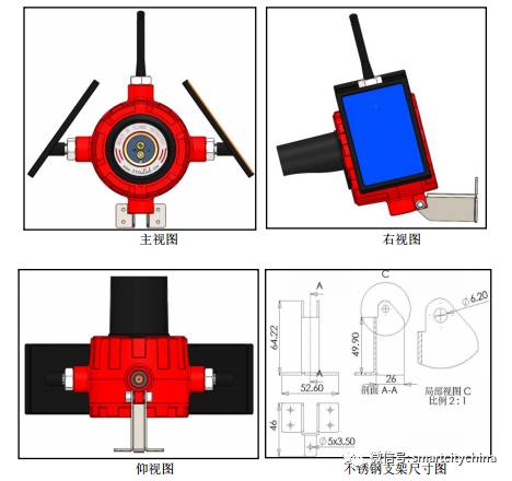
Figure 3.7 Structural Installation Diagram of the Detector
3.2.3 System Flame Detection Capability Indicators
Flame detection: See Table 3.1 and Figure 3.8
Table 3.1 Level I Sensitivity Distance and Equivalent Ignition Area List
|
Distance |
Ignition Area |
|
5m |
Flickering Flame of a Lighter |
|
10m |
13.2*13.2cm |
|
25m |
33*33cm |
|
50m |
66*66cm |
|
75m |
99*99cm |
|
100m |
132*132cm |
|
200m |
264*264cm |
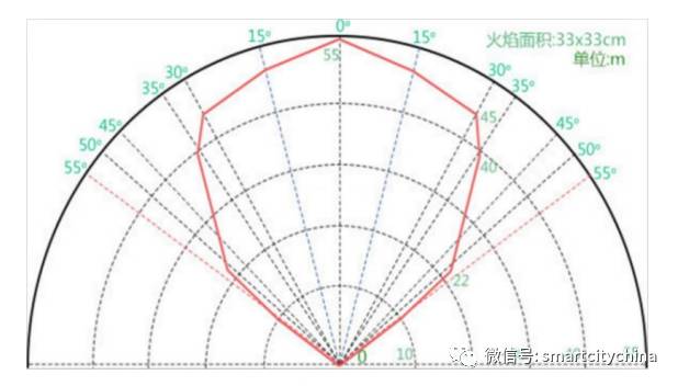
Figure 3.8 Horizontal Angle Sensitivity Diagram
3.2.4 Working Principle
Flame combustion generates thermal radiation in the infrared band, light radiation in the visible light band, and radiation in the ultraviolet band. The higher the flame temperature, the more infrared radiation is produced. The radiation of flames burning different materials has different distributions in each band, but for carbon-containing materials, their flames will have a very high energy distribution in the mid-infrared band, and the CO2 generated during combustion can effectively absorb infrared radiation in this band. The flame spectrum of hydrocarbons is shown in Figure 3.9.
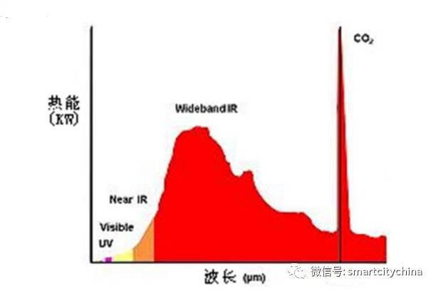
Figure 3.9 Hydrocarbon Flame Radiation Spectrum
Additionally, when sunlight passes through the atmosphere, the energy in the near spectrum of sunlight is significantly absorbed by the CO2 in the atmosphere, resulting in a significant reduction. The infrared intensity of this spectrum in the atmosphere is relatively weak. The infrared radiation spectrum distribution of sunlight is shown in Figure 3.10. Therefore, the spectrum near CO2 is an important band for infrared flame detection.
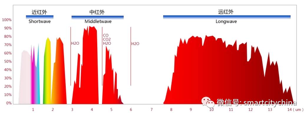
Figure 3.10 Infrared Spectrum Distribution of Solar Radiation
By selecting infrared sensors at the wavelength of CO2, the infrared characteristics of carbon-containing materials burning can be detected. By selecting other wavelengths of pyroelectric infrared sensors, using multi-parameter analysis and mathematical calculation techniques, mainly utilizing the flickering analysis of flame light signals and narrow frequency threshold signal analysis of infrared light, it can accurately determine flame combustion and effectively reduce false alarm probability.
3.2.5 JTG-HW/YK Series Flame Detector – Performance Indicators
The specific performance indicators of the JTG-HW/YK series flame detectors are detailed in the table below, described from aspects such as basic information, sensing recognition, communication parameters, structural composition, and working environment.
Table 3.2 JTG-HW/YK Series Flame Detector – Performance Indicators
|
Basic Information |
Product Model |
JTG-HWJ100BN |
JTG-HWJ100SN |
JTG-HWJ200BN |
JTG-HWJ200SN |
|
Product Chinese Name |
Single-channel Standard Infrared Flame Detector |
Single-channel Enhanced Infrared Flame Detector |
Dual-channel Standard Infrared Flame Detector |
Dual-channel Enhanced Infrared Flame Detector |
|
|
Sensing Recognition |
Number of Infrared Channels |
Single Channel |
Single Channel |
Dual Channel |
Dual Channel |
|
Horizontal Field Angle |
≤110° |
≤110° |
≤110° |
≤110° |
|
|
Detection Distance |
≤100m (132*132cm2) |
≤100m (132*132cm2) |
≤100m (132*132cm2) |
≤100m (132*132cm2) |
|
|
Response Time |
≤30s |
≤15s |
≤15s |
≤5s |
|
|
Communication |
Carrier Frequency |
433Mhz (UHF) |
433Mhz (UHF) |
433Mhz (UHF) |
433Mhz (UHF) |
|
Network Scale |
≤250 Nodes |
≤250 Nodes |
≤250 Nodes |
≤250 Nodes |
|
|
Structure |
Dimensions |
245*85*230mm (without sunshade) |
245*85*230mm (without sunshade) |
245*85*230mm (without sunshade) |
245*85*230mm (without sunshade) |
|
Weight |
1.2Kg |
1.2Kg |
1.2Kg |
1.2Kg |
|
|
Shell Material |
Die-cast Aluminum Alloy ADC12 |
Die-cast Aluminum Alloy ADC12 |
Die-cast Aluminum Alloy ADC12 |
Die-cast Aluminum Alloy ADC12 |
|
|
Protection Level |
IP67 |
IP67 |
IP67 |
IP67 |
|
|
Working Environment |
Temperature |
-20℃~+70℃ |
-20℃~+70℃ |
-20℃~+70℃ |
-20℃~+70℃ |
|
Humidity |
0%~100% (No Condensation) |
0%~100% (No Condensation) |
0%~100% (No Condensation) |
0%~100% (No Condensation) |
3.2.6 Flame Detector Deployment Installation Requirements
Our company will deploy fire detectors in high fire risk forest areas and areas with frequent tourist activities based on on-site reconnaissance information, forming a fire prevention warning monitoring zone.
Deployment of flame detectors should follow these requirements:
(1) Detector Spacing: Deploy within 50~100m visibility range of the detector flame probe (specific spacing determined based on on-site terrain).
(2) Detector Redundancy: Adjacent detectors should be arranged in a matrix, overlapping within communication distance redundancy range to avoid network interruption due to individual detector failure. As shown in Figure 3.12:
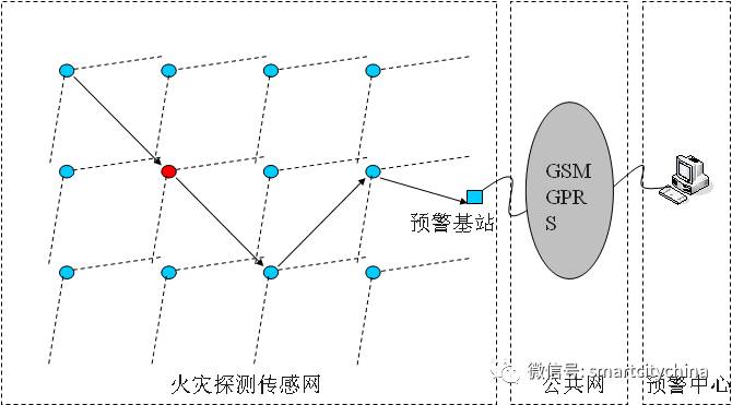
Figure 3.12 Sensor Network Detector Deployment Diagram
(3) Detector Orientation: The detector antenna should face upwards, and the detector fire probe should face the fire observation area with a horizontal 10-degree downward viewing angle.
(4) Detector Height: The detector should be at least 3m above the ground, with a recommended height of 4m.
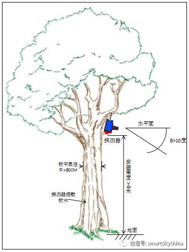
Figure 3.13 Installation Diagram on Tree Trunk
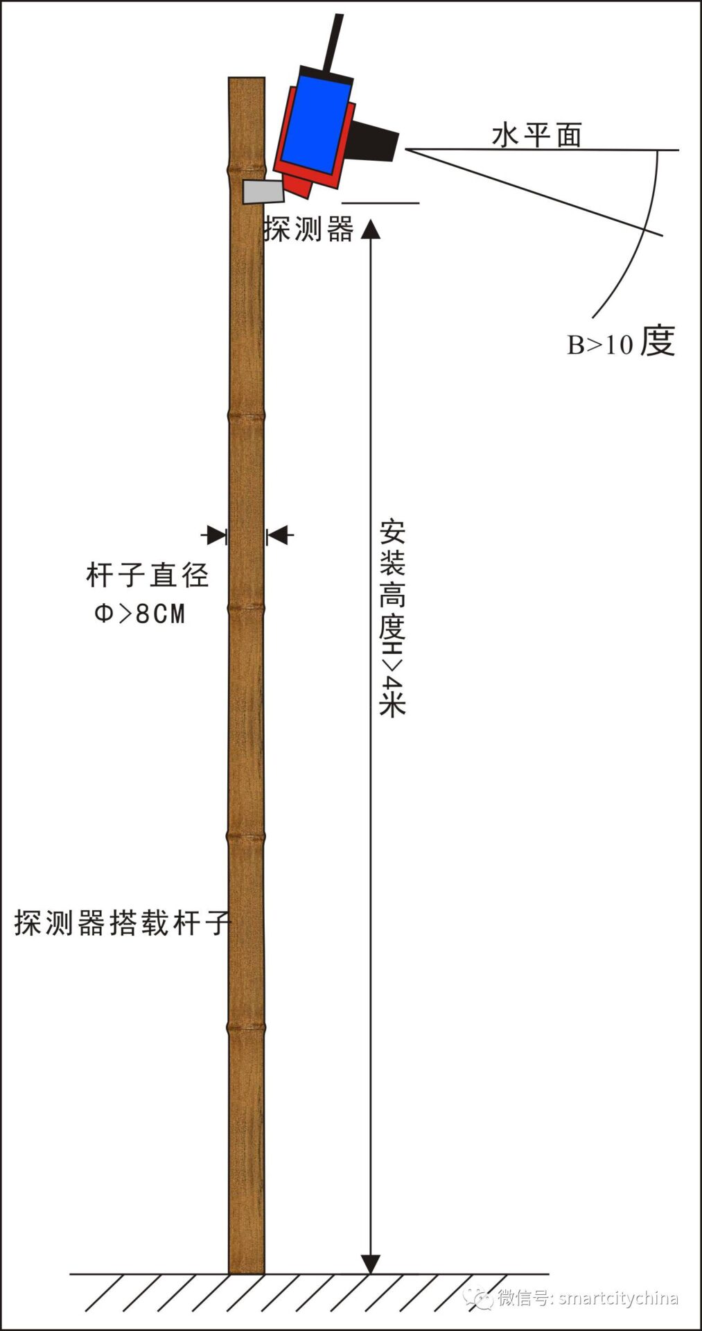
Figure 3.14 Installation Diagram on Vertical Pole
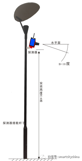
Figure 3.15 Installation Diagram on Street Light
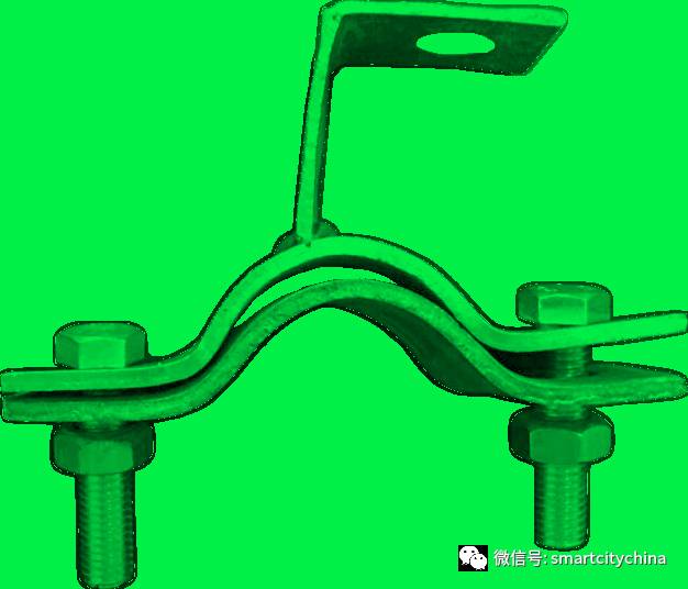
Figure 3.16 Installation of Green Street Light and Vertical Pole
3.3 IOT-G Type IoT Data Gateway – Product Introduction
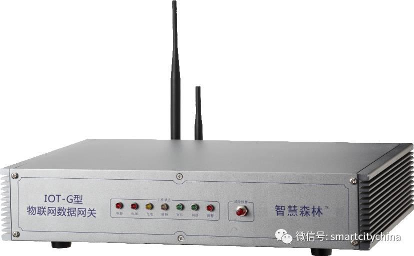
Figure 3.17 IOT-G Type IoT Data Gateway
The IOT-G type IoT data gateway (as shown in Figure 3.13) integrates network fire situation reception, remote fire situation forwarding, detector network management, unattended early warning, and fire situation alarm prompts into one system. It has high reliability, high stability, and self-recovery characteristics, supporting unattended fire situation early warning monitoring.
n Fire Situation Reception: Deployed near the sensor network within 200~500m, capable of receiving fire situation messages from the sensor network;
n Remote Transmission: Sends to the forestry ecological safety emergency command platform via GSM short message and wired network TCP/IP protocol;
n Unattended: Directly sends fire location via GSM short message or wired network TCP/IP protocol to the early warning platform;
n Fire Situation Alarm: Directly drives the alarm light to issue a strong audible and visual alarm, with a range greater than 50m;
n Network Management: Can initiate network routing, data collection, and network inspection commands to troubleshoot detector faults;
n Backup Power: Built-in automatic charging battery, can support more than 24 hours of operation;
n Automatic Recovery: If an abnormal operation occurs, it automatically restarts within 10 seconds to prevent measurement and control interruption and avoid maintenance.
3.3.1 Wireless Communication System
The wireless communication of the IOT-G type IoT data gateway uses 433Mhz (UHF), LoRa wireless technology dual wireless communication system, with a high degree of wireless communication integration, capable of fully integrating into the construction of Yongchuan Smart City.
(1) LoRa Low-Power Wide Area Network Communication Technology Advantages
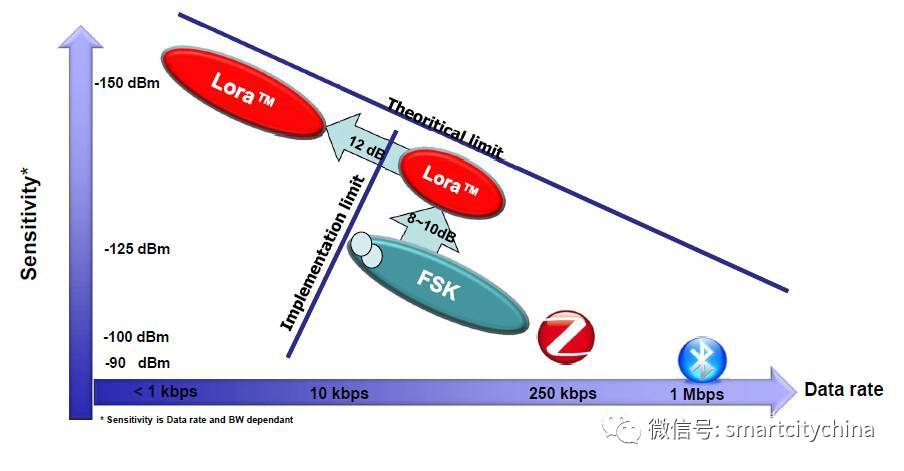
Figure 3.18 LoRa Technology Characteristics
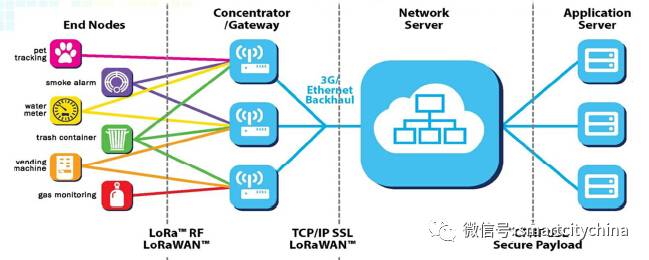
Figure 3.19 LoRa Network Architecture
(1) Greatly improves reception sensitivity and reduces power consumption
A link budget of up to 157db allows for communication distances of up to 15 kilometers (depending on the environment). Its receiving current is only 10mA, with a sleep current of 200nA, greatly extending battery life.
(2) Gateways/Concentrators based on this technology support multi-channel multi-data rate parallel processing, with large system capacity
The gateway serves as a bridge between nodes and the IP network (via 2G/3G/4G or Ethernet). Each gateway can handle 5 million communications between nodes per day (assuming each transmission is 10Bytes with 10% network occupancy). If the gateway is installed at existing mobile communication base stations, with a transmission power of 20dBm (100mW), it can cover about 2 kilometers in densely built urban environments, while in less densely populated suburban areas, coverage can reach 10 kilometers.
(3) The system based on terminals and concentrators/gateways can support distance measurement and positioning
LoRa measures distance based on the signal’s air transmission time rather than traditional RSSI (Received Signal Strength Indicator), while positioning is based on measuring the time difference of air transmission from multiple points (gateways) to one point (node). Its positioning accuracy can reach 5m (assuming a range of 10km).
3.3.2 Fire Detection Sensor Network IoT Gateway Deployment Scheme
In this scheme, the IoT gateway (Boda Guangtong) is deployed within the forest management station, responsible for managing all fire detectors. The installation wiring of the IoT gateway is shown in Figure 3.14.
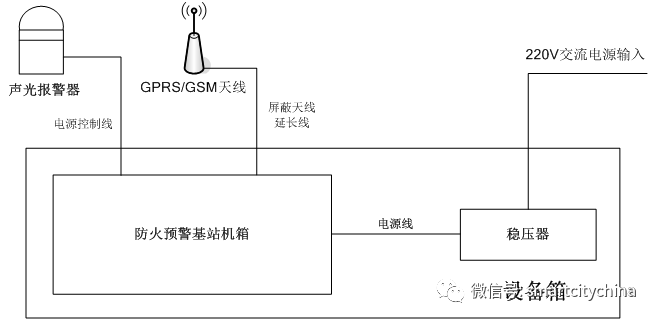
Figure 3.20 Installation Diagram of Fire Detection Sensor Network Gateway
3.3.3 IoT Gateway Installation
(1) Installation Point Selection
The IoT gateway must be within the range of the wireless infrared flame detectors’ sensor network, chosen in a sheltered place with access to mains electricity, and must meet the following conditions:
n The installation site must have a 220V AC power supply interface;
n The installation site must have mobile communication signal, with a mobile test of no less than 3 bars;
n The installation site must be able to receive sensor network signals;
n The installation site must be protected from rain, snow, wind, sand, and dust;
n The installation site must not have flammable, explosive, or corrosive materials present.
3.3.4 IOT-GJ431BF IoT Gateway – Performance Indicators
Table 3.3 provides specific performance indicators of the IoT gateway, described from aspects such as basic information, remote data, short-distance wireless communication, power supply, and structure.
Table 3.3 IOT-GJ431 Series IoT Gateway (Boda Guangtong) – Performance Indicators–
|
Basic Information |
Product Model |
IOT-GJ431BF |
IOT-G*431S |
IOT-G*431OA |
IOT-G*431OS |
SR-300 |
|
Product Name |
Standard IoT Gateway |
Luxury IoT Gateway |
Outdoor Mains IoT Gateway |
Outdoor Solar IoT Gateway |
IoT Early Warning Base Station |
|
|
Remote Data |
Communication Interface |
GSM/SMS/GPRS |
GSM/SMS/GPRS (Optional) |
GSM/SMS/ GPRS |
GSM/SMS/ GPRS |
GSM/SMS/ GPRS |
|
Communication |
Working Frequency: 900/1800Hz; |
Working Frequency: 900/1800Hz; |
Working Frequency: 900/1800Hz; |
Working Frequency: 900/1800Hz; |
Working Frequency: 900/1800Hz; |
|
|
WIFI (Optional) |
||||||
|
Working Frequency: 2.4GHz; |
||||||
|
RJ45 (Optional) |
||||||
|
Ethernet: IEEE802.3(u); |
||||||
|
Short-Distance Wireless Communication |
Carrier Frequency |
433Mhz (UHF) |
433Mhz (UHF)
|
433Mhz (UHF)
|
433Mhz (UHF)
|
433Mhz (UHF) ) |
|
Network Scale |
≤250 Nodes |
≤250 Nodes |
≤250 Nodes |
≤250 Nodes |
≤250 Nodes |
|
|
Power Supply |
Main Power Supply |
220V Mains Power Supply |
220V Mains Power Supply |
220V Mains Power Supply (Optional Outdoor Installation Bracket) |
Solar Power Supply |
220V Mains Power Supply |
|
Working Voltage Range: |
Working Voltage Range: |
Working Voltage Range: |
*Optional Outdoor Installation Bracket* |
Working Voltage Range: |
||
|
100~240V,1.6A/50~60Hz |
100~240V,1.6A/50~60Hz |
100~240V,1.6A/50~60Hz |
100~240V,1.6A/50~60Hz |
|||
|
Backup Power |
Lead-acid Battery |
Lead-acid Battery |
No |
Lead-acid Battery |
Lead-acid Battery |
|
|
Structure |
Shell Material |
Aluminum Alloy |
Aluminum Alloy |
Aluminum Alloy |
Aluminum Alloy |
Aluminum Alloy |
|
Shell Protection |
IP51 |
IP51 |
IP65 |
IP65 |
IP51 |
|
|
Working Temperature |
0~50℃ |
-20~50℃ |
-40~60℃ |
-40~60℃ |
0~50℃ |
|
|
Working Humidity |
10%~90% (No Condensation) |
10%~90% (No Condensation) |
0%~100% (No Condensation) |
0%~100% (No Condensation) |
3.3.5 IOT-G-L431O Outdoor IoT Gateway
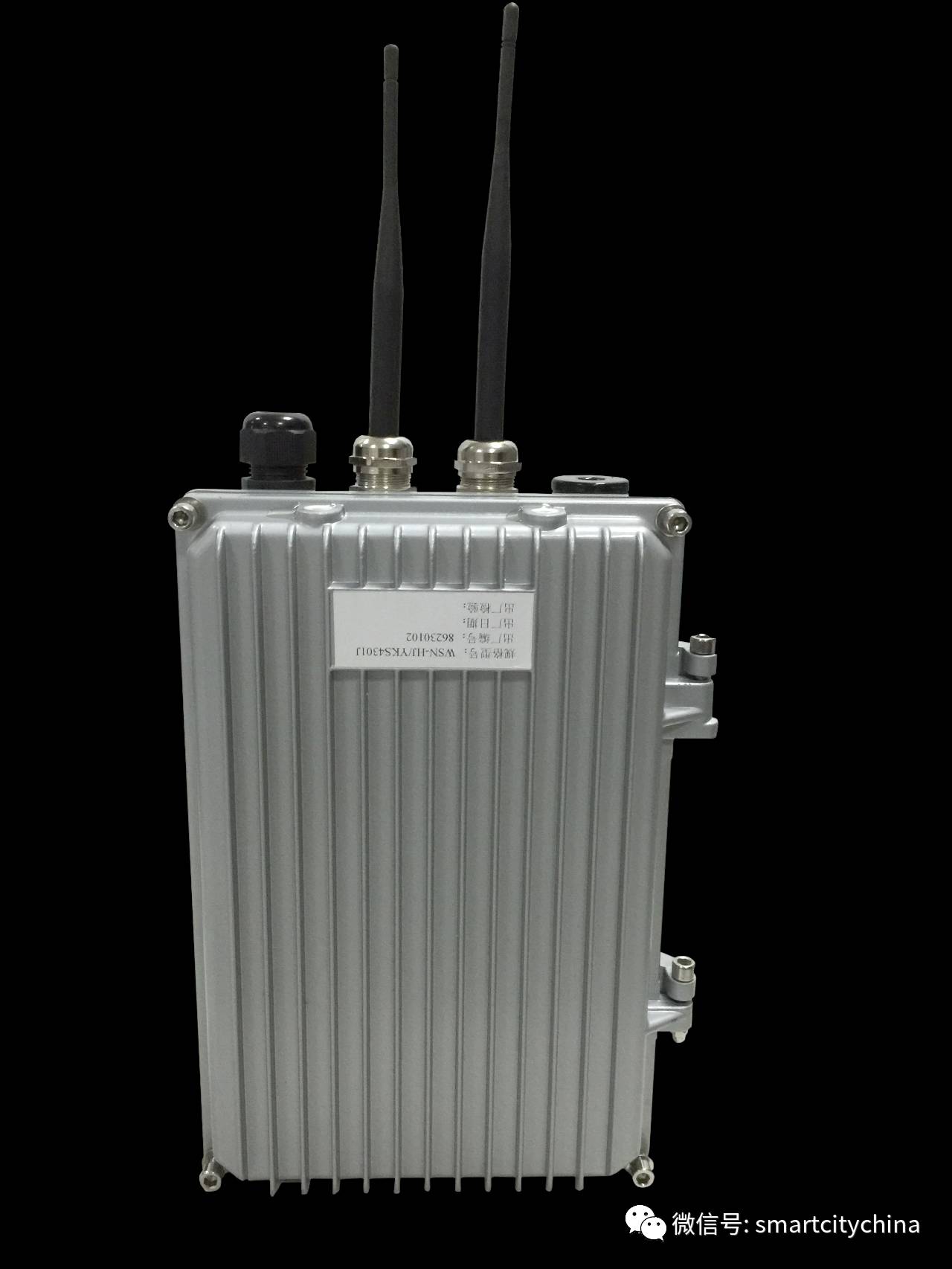
Figure 3.21 IOT-G-L431O Outdoor IoT Gateway
The IOT-G-L431O outdoor IoT gateway integrates network fire situation reception, remote fire situation forwarding, detector network management, unattended early warning, and fire situation alarm prompts into one system, with high reliability, high stability, and self-recovery characteristics, supporting unattended fire situation early warning monitoring. It has all indoor gateway functions while requiring no mains electricity, suitable for all complex outdoor environments.
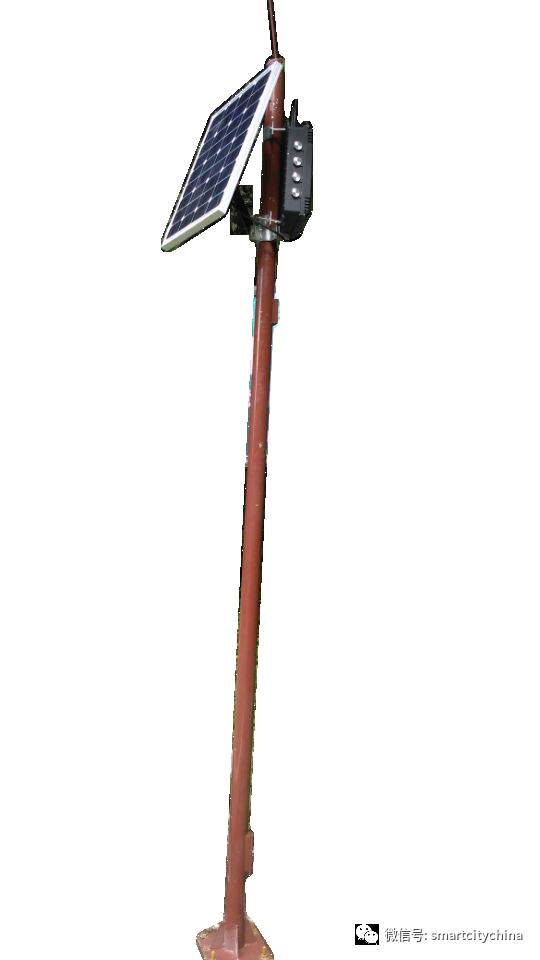
Figure 3.22 IOT-G-L431O Outdoor IoT Gateway Installation Finished Product Diagram
(1)Outdoor Gateway Configuration Solar Panel (GHGN-D50WK)
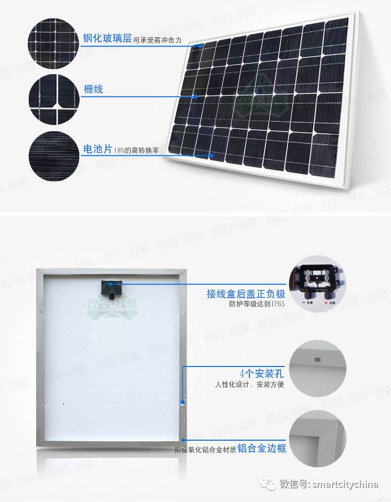
Figure 3.23 GHGN-D50WK Type Solar Panel
The GHGN-D50WK type solar panel is a green energy power supply device with the following characteristics:
l Safe and Reliable: Pollution-free, noiseless, environmentally friendly, beautiful, low failure rate, and requires minimal maintenance;
l Green Power Supply: The solar panel can generate electricity as long as there is sunlight, truly a green energy supply, not limited by geographic location, does not consume fuel, has no mechanical moving parts, short construction period, and can be built in any size safely and reliably;;
l Working Temperature Range:-40℃~85℃;
Usage Parameters: Output Power 50W, Working Voltage 18V.
In response to the booming market trend of facial recognition technology applications, Smart City China and facial recognition experts within the Smart City China Micro Academy group will hold an online live broadcast and micro forum on the smart applications of facial recognition technology on January 21-22, 2017 (Saturday and Sunday) from 8 PM to 9 PM, each night for 1 hour, with online live broadcast + group interaction.
Main content of the live broadcast and micro forum:1. Latest development trends in facial recognition technology;2. Smart business application models of facial recognition technology;3. Big data operation models of facial recognition technology;4. Main providers of facial recognition solutions.
Suitable audience:Facial recognition technology providers, product providers, solution providers, and big data service operators
Registration Method:
1. Scan the QR code below to pay and join the Smart City China Micro Academy group;

2. Take a screenshot of the transaction record in your wallet, add WeChat ID shiyong008 and send the screenshot message, after confirmation, you will be invited to join the Smart City China Micro Academy group;
3. Report: Name+ Organization+Main Smart City Business+ Phone+Email, for communication and cooperation within the group;
4. One hour before the meeting, obtain the meeting live room password and live entry link in the group.
5. Participants will receive the outline of the lecture in the group before the meeting;
6、Participants need to pay a material fee of two hundred yuan for the complete “Facial Recognition System Integration Engineering Lecture Notes (includingPPT, top-level design and overall solution), must pay the material fee of two hundred yuan;
7. Participants should download the Qianliao APP before the meeting, and enter the live entry using the obtained password;
8.Those who fail to register in time before the meeting can listen to the recording and obtain shared lecture notes in the group.
Smart City China
Cooperation Email: [email protected]
For more information, please visit the Smart City series of classics, and you can also apply to join the group friends directory Smart System Community.
“Smart City China Selected Collection (2014-2016)” is available upon request, send email to: [email protected] report: Name + Organization + Main Smart City Business and Products, Technologies, Solutions + Phone + Email, for free access.