Dell has been committed to improving their IoT devices, namely gateway devices, which mainly integrate and process information data. Dell’s latest product, the 5100, aims to provide a powerful smart gateway that ensures normal operation even in industrial environments and under extreme temperatures.
The Dell smart gateway 5100 operates in industrial environments and can be wall-mounted or installed on a DIN rail. It features a fanless solid-state heat dissipation design, with an operating temperature range of -30℃ to 70℃. Its casing achieves an IP65 level of water and dust resistance to ensure the product can be used in harsh environments. Therefore, in the case of limited volume, optimizing the air vents, component positions, and the arrangement of heat sinks to improve the product’s heat dissipation is crucial.

Figure 1 Dell Smart Gateway 5100
Dell optimized the thermal dissipation of the smart gateway 5100 using FloTHERM software simulations.

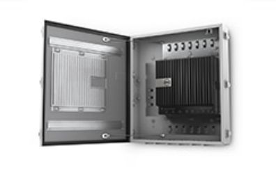
Figure 2 DIN Rail Installation and Wall Mount Installation
Physical Model Introduction: The smart gateway 5100 consists of a PCB board measuring 190*185mm, DDR components, LAN components, and WAN components, with a CPU power of 5W on the PCB, and a total power of 10.7W for other components. The maximum allowable temperature for the CPU is 100℃. The heat generated by the components is mainly dissipated through conduction to the surrounding solid walls.
Heat Sink Optimization: The heat sink of the smart gateway 5100 is installed at the top of the aluminum panel, with a maximum size of 180*140mm. The height, number, and spacing of the heat sink fins are variable parameters. The traditional method involves sequentially constructing models with different parameters and testing them, which is inefficient. Therefore, the “smart heat sink” module of FloTHERM software is used for thermal design to achieve optimal distribution of the heat sink fins.
Ventilation Optimization: The design of the ventilation openings on the surface of the smart gateway is also crucial for its thermal dissipation. However, traditional testing methods are time-consuming and labor-intensive. The visualization tools of FloTHERM software help users directly view the flow distribution and temperature distribution of the product, identifying thermal blind spots, which can easily assist in designing the layout of the product’s shell and ventilation openings. Figure 3 shows a visualization of particle flow from the software, which is similar to smoke line testing, displaying flow distribution and temperature distribution.
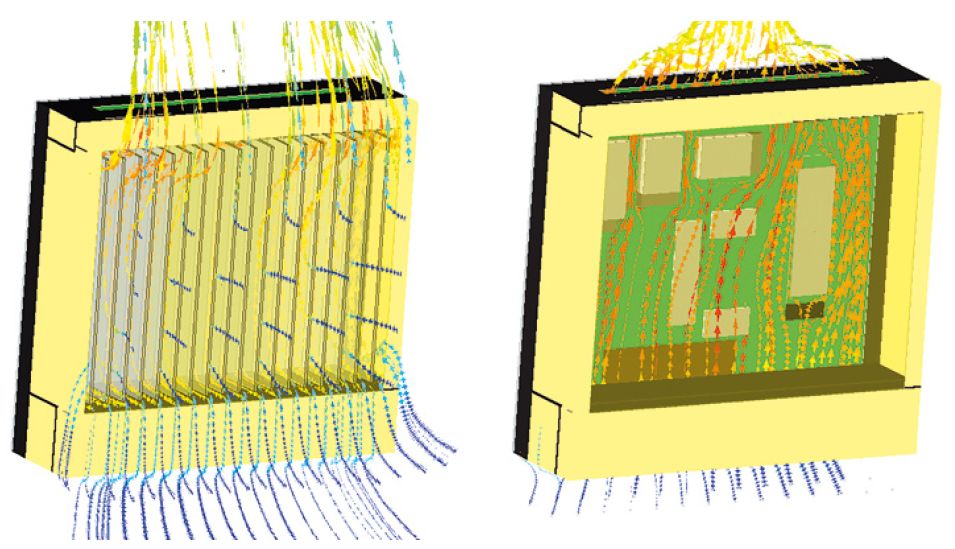
Figure 3 Airflow Cooling Heat Sink (left), Motherboard (right)
After completing the optimization design of the heat sink and ventilation openings, the “advanced simulation result dynamic visualization post-processing” module of FloTHERM software can provide the temperature distribution on the upper and lower surfaces of the product’s motherboard, as well as the temperature distribution and heat flux distribution at any cross-section. As shown in Figure 4, the left image shows the temperature distribution across the SoC component, clearly indicating that the high-temperature area is located at the CPU. The right image shows the heat flux cloud map of the heat dissipation process of the gap-filling pad and heat sink for the CPU, displaying the heat conduction path, which helps users identify the causes of excessive component temperatures. It is recommended to continue using dimensionless thermal flow bottlenecks (Bn) & thermal flow shortcuts (Sc) for further optimization analysis.
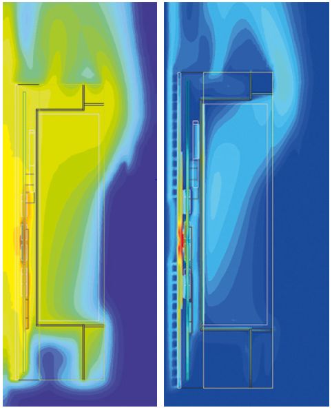
Figure 4 Cross-section Temperature Distribution (left), Heat Flux Distribution (right)
“FloTHERM enables us to quickly create 3D models without detailed drawings. We leveraged FloTHERM model parameters to rapidly create detailed thermal models and parameter studies. This has allowed us to avoid costly modifications later in the design process.” Chris Helberg, Systems Architect, Thermal, Dell and Prasad Tota.
This article is organized and published by Haiji.
-END-
FloTHERM Video Collection
http://edu.yanfabu.com/course/explore/Flotherm
FloTHERM Engineering Application Case Collection
http://edu.yanfabu.com/course/1577
Thermal Design Technology QQ Group for Electronic Devices
102886397

FloTHERM Technical Communication WeChat Group

Free Quick Trial: tool.yanfabu.com Haiji Technology Customer Service QQ: 2378663865 Haiji Technology Customer Service WeChat: hikeytech1996