Oscilloscopes are not very expensive these days, and it would be a waste to buy one just for show. Testing drive waveforms with it seems unnecessary.
I always think about how to use it for tasks that help our repair work or improve repair efficiency. For detecting inter-turn short circuits in switch power supply transformers, there doesn’t seem to be a quick method. This issue is not like capacitors or tubes; for inter-turn short circuits, a multimeter cannot measure anything effectively. Many switch transformers fail due to inter-turn short circuits in the N1 winding.
In practical operation, it seems difficult to determine what level of ringing waveform is considered good and what level is considered bad.
Today, I had a sudden idea: I can input a square wave into the N1 winding and then measure whether there is a waveform output from the other windings. Isn’t this a convenient way to test the transformer?
I immediately conducted an experiment, and it was indeed very intuitive and useful!
I’m sharing this good method with everyone. If many friends already know this method, then I guess I’m outdated.
You can directly use the built-in 1kHz square wave test signal output from the oscilloscope as the signal source, without needing to configure an additional signal source.
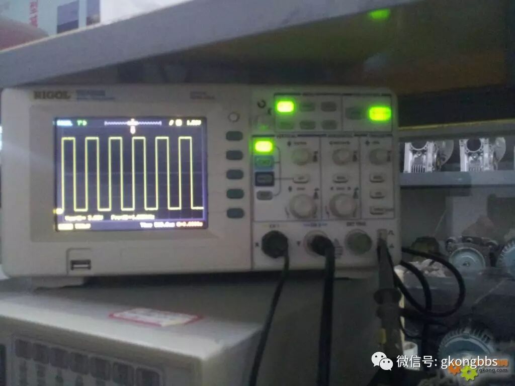
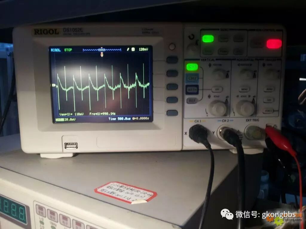
For a tested transformer, connect the signal input to the N1 winding, and measure that the other windings all have square wave signals, although there will be some distortion.
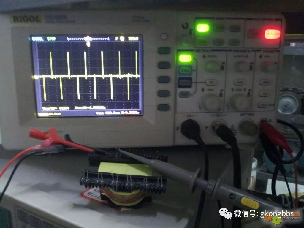
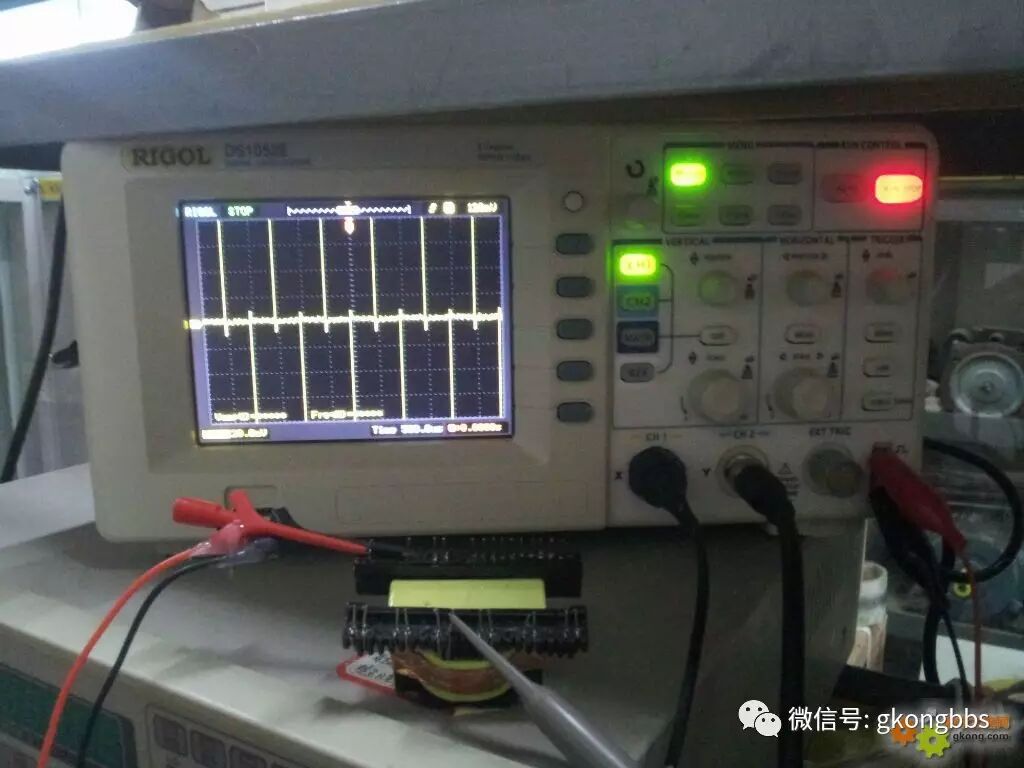
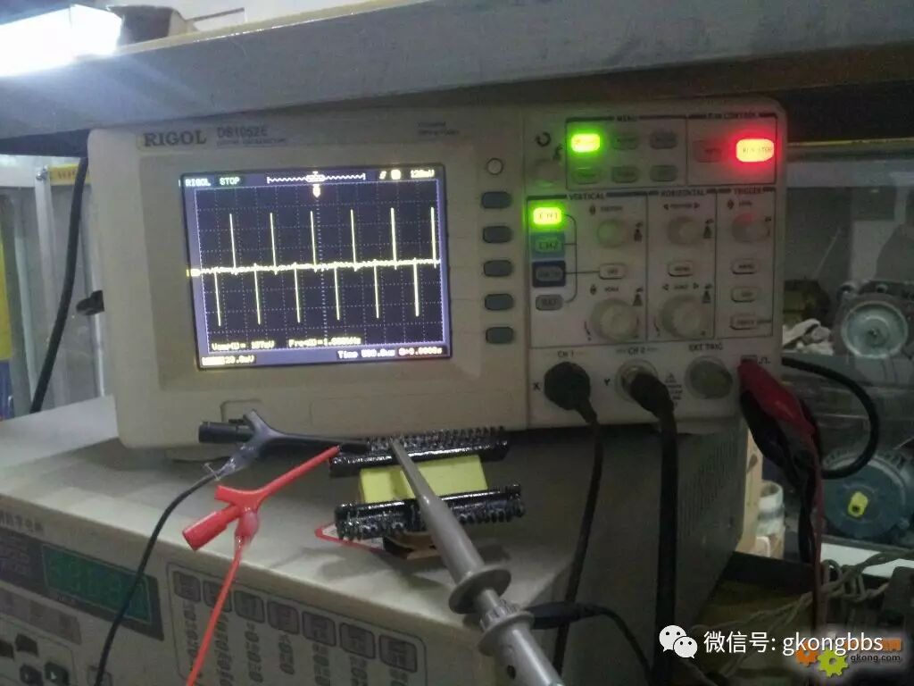
N1 winding transformers with inter-turn short circuits show no response in the other windings when a square wave is input.
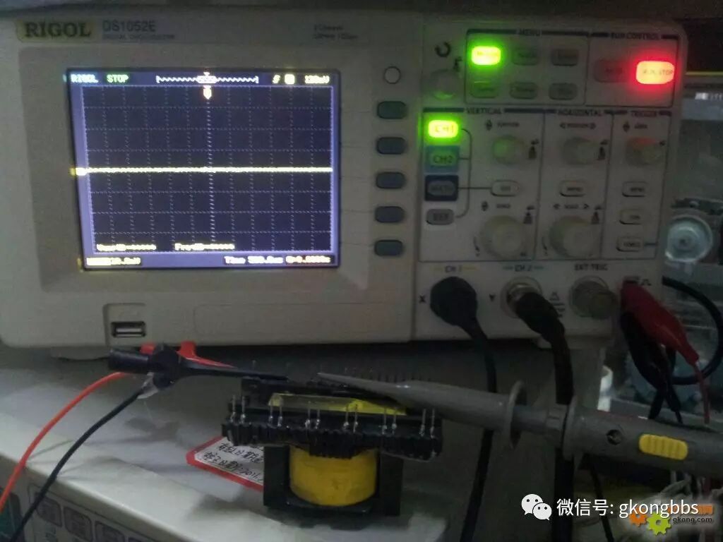
Online measurement is also possible; although there is some distortion, it can be easily identified.
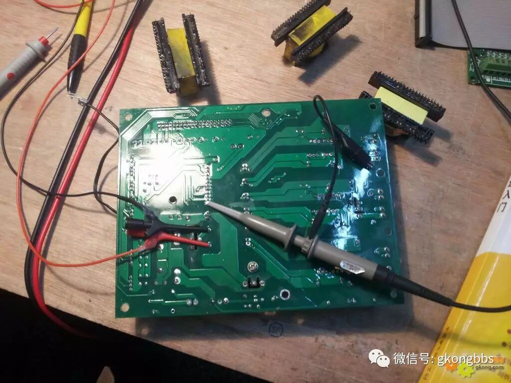
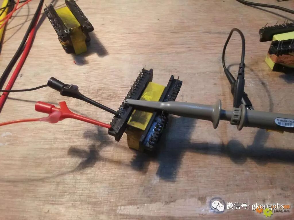
It is very necessary and useful to make some test leads yourself.
—————–End—————-
Source: Industrial Control Forum
Submission email: [email protected]. Accepted submissions will receive a fee!
Long press the QR code to follow the forum master