Many electricians are accustomed to using a shake table to measure the condition of motors in their daily work, which is undoubtedly a common and relatively safe testing method. Today, I will share how to use a multimeter to measure the condition of motors, so that in case a shake table is not available, you can still assess the situation without delaying your work progress!
Measurement Method for Three-Phase Motors:
Set the digital multimeter to the 200Ω range and measure the resistance between the three-phase power lines of the motor in pairs. If the resistance values from the three measurements are equal or very close, it indicates that the three-phase windings are well connected.
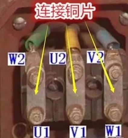
Next, open the motor’s junction box and remove the connecting copper pieces on the terminals, which disconnects the connections of the U, V, and W windings. Set the multimeter to the maximum resistance range and measure the resistance between any two of the U, V, and W windings. If the resistance values all show infinity, it indicates that the motor’s inter-phase insulation is normal.
Finally, using the multimeter’s maximum resistance range, measure the resistance between any of the U, V, W terminals and the motor casing. If the resistance values are all infinite, it indicates that the motor insulation is fine, and it can be powered on for a startup test.
Measurement Method for Single-Phase Motors:
When measuring a single-phase motor, set the digital multimeter to the 2K range and first measure the resistance of the main winding, which is generally in the range of tens to hundreds of ohms, varying according to the motor’s power.
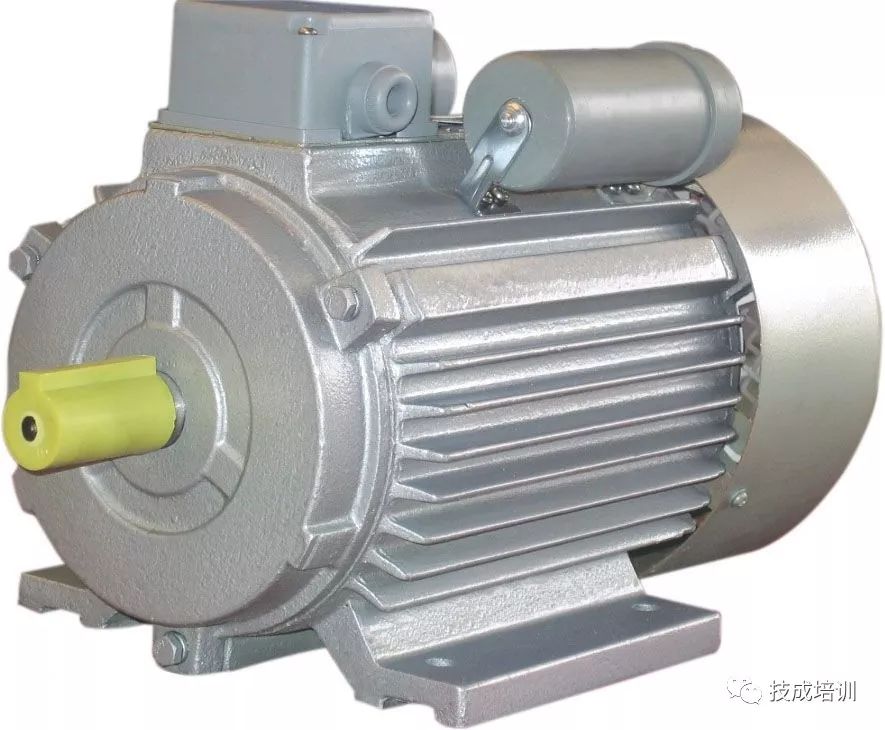
The resistance of the auxiliary winding should be slightly larger or the same as that of the main winding. If the resistance values of both the main and auxiliary windings are normal, measure the insulation between the main and auxiliary windings. Set the multimeter to the maximum resistance range, and with the main and auxiliary windings disconnected, connect one probe to any terminal of the main winding and the other probe to any terminal of the auxiliary winding. An infinite insulation resistance is normal. Finally, also measure the insulation resistance between the two windings and the casing. One probe should connect to the winding, and the other probe should connect to a conductive part of the motor casing, showing infinity is normal.
Source: Jicheng Training