“Assembly Language”, 3rd Edition by Wang Shuang
Chapter 15: External Interrupts (Page 285)
Experiment 15: Install a new INT 9 interrupt routine
Install a new INT 9 interrupt routine that, under DOS, displays a full screen of “A” when the “A” key is pressed and held down; other keys are processed normally.
Tip: The scan code generated when a key is pressed is called the make code, and the scan code generated when a key is released is called the break code. Break code = make code + 80H.
———————–
Summary of Instruction Set
We summarize the instruction set of the 8086 CPU. Readers who wish to understand the usage of various instructions in the 8086 instruction set in detail can refer to the relevant instruction manuals.
The 8086 CPU provides the following major categories of instructions:
1. Data Transfer Instructions
For example, mov, push, pop, pushf, popf, xchg, etc., are all data transfer instructions that implement single data transfers between registers and memory, or between registers.
2. Arithmetic Operation Instructions
For example, add, sub, adc, sbb, inc, dec, cmp, imul, idiv, aaa, etc., are all arithmetic operation instructions that perform arithmetic operations on data in registers and memory. Their execution results affect the flags in the status register: sf, zf, of, cf, pf, af.
3. Logical Instructions
For example, and, or, not, xor, test, shl, shr, sal, sar, rol, ror, rcl, rcr, etc., are all logical instructions. Except for the not instruction, their execution results affect the relevant flags in the status register.
4. Transfer Instructions
Instructions that can modify the IP, or simultaneously modify CS and IP, are collectively referred to as transfer instructions. Transfer instructions are divided into the following categories:
(1) Unconditional transfer instructions, such as jmp;
(2) Conditional transfer instructions, such as jcxz, je, jb, ja, jnb, jna, etc.;
(3) Loop instructions, such as loop;
(4) Procedures, such as call, ret, retf;
(5) Interrupts, such as int, iret;
5. Processor Control Instructions
These instructions set the status register or other processor states, such as cld, std, cli, sti, nop, clc, cmc, stc, hlt, wait, esc, lock, etc., are all processor control instructions.
6. String Processing Instructions
These instructions process bulk data in memory, such as movsb, movsw, movsd, cmps, scas, lods, stos, etc. To conveniently use these instructions for bulk data processing, they need to be used in conjunction with prefix instructions like rep, repe, repne, etc.
=============
Example code is as follows:
;"Assembly Language", 3rd Edition by Wang Shuang; Chapter 15: External Interrupts (Page 285); Experiment 15: Install a new INT 9 interrupt routine; Requirement: When the "A" key is pressed, if released, display a full screen of "A", other keys are processed normally
assume cs:code, ss:stack
stack segment    db 128 dup(0)
stack ends
code segment           ; Set up stack segment
start: mov ax, stack           mov ss, ax           mov sp, 128           ; Copy new int9 code to 0:204H
           mov ax, code           mov ds, ax           mov si, offset int9_begin           mov ax, 0           mov es, ax           mov di, 204H           mov cx, offset int9_end - offset int9_begin           cld            rep movsb           ; First save the original int9 interrupt vector to 0:200H           push es:[9*4]           pop es:[200H]           push es:[9*4+2]           pop es:[202H]           ; Then modify the entry address of int9           cli  ; Disable interrupts while modifying           mov word ptr es:[9*4], 204H           mov word ptr es:[9*4+2], 0           sti           ; End of installation program           mov ax, 4c00H           int 21H                ; New int9 interrupt routine    int9_begin: push ax                push bx                push cx                push es                in al, 60H      ; Read the scan code of the key                pushf           ; Simulate calling the original int9 interrupt                call dword ptr cs:[200H]  ; New int9 executes (cs)=0                cmp al, 1EH+80H ; 1EH is the make code for key A, break code after adding 80H                jne int9_ret    ; If not the break code for key A, jump out                mov ax, 0B800H  ; Video memory segment address                mov es, ax                mov bx, 0                mov cx, 2000        show_A: mov byte ptr es:[bx], 'A'                 add bx, 2                loop show_A      int9_ret: pop es                pop cx                pop bx                pop ax                       iret      int9_end: nop        code ends
start
Debugging process as follows:
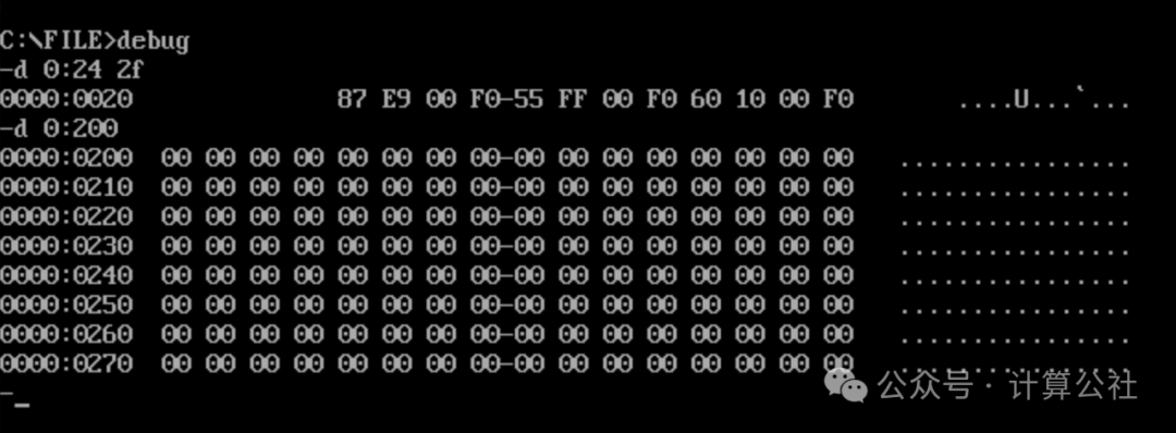
1. Before installing the new int9, first check the interrupt vector and the data at 0:200H, as shown in the figure below.
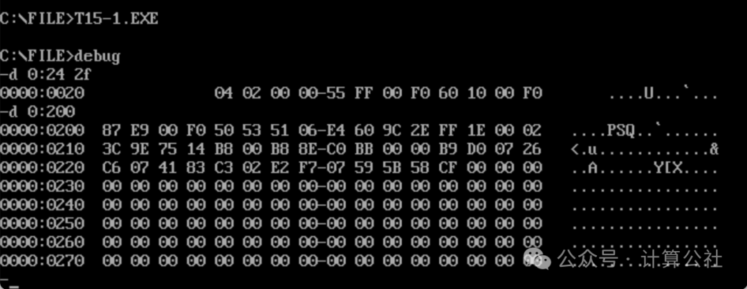
2. After installation, the 9H interrupt vector is set to 0000:0204H, the original int9 interrupt vector F000:E987H is saved to 0:200H, and the new int9H code has also been correctly copied, as shown in the figure below.
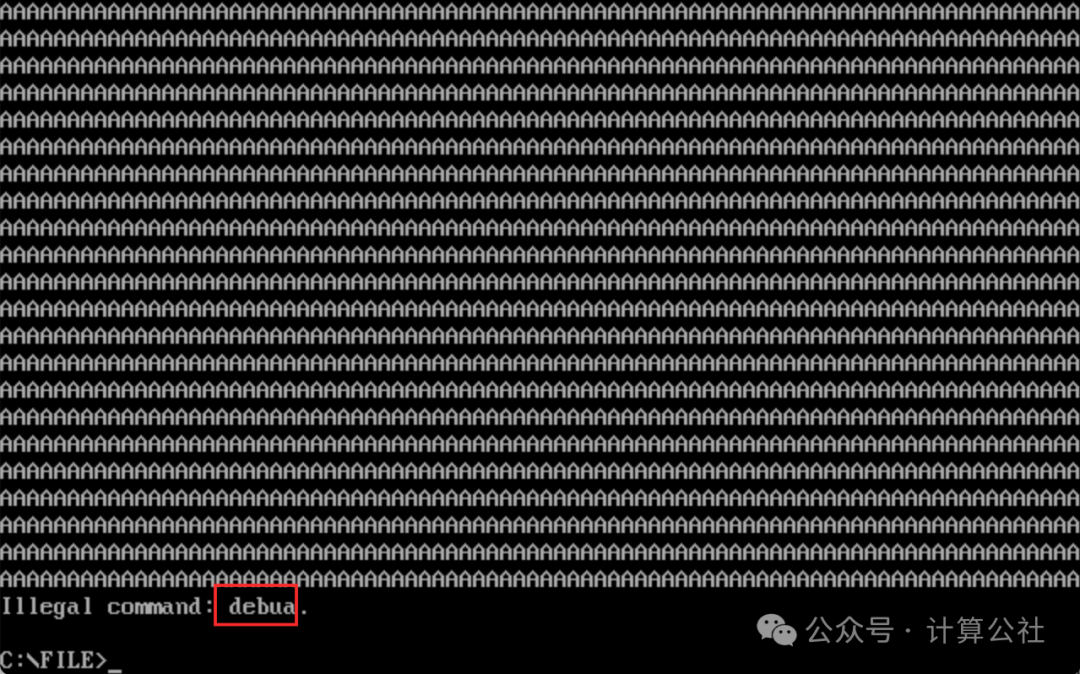
3. When the “A” key is pressed and released, a full screen of “A” is displayed, achieving the experiment’s requirements. As shown in the figure below.

4. In the above figure, before the full screen output of “A”, the keys D, E, B, U were displayed normally on the screen, and pressing the “A” key also displayed normally; however, upon release, it displayed a full screen of “A”. Pressing enter again resulted in an error “Illegal command” because “debua” is not a valid instruction, as shown in the figure below. Debugging verification is complete.