1. Introduction
In embedded development, the design of drivers is mostly about implementing data flow links. Simply put, a driver is a “data mover”, transferring data from the application layer to the hardware interface for sending, and moving data from the hardware interface back to the specified space in the application layer. Of course, a more efficient implementation aims to reduce data movement, meaning not acting as a “data mover”, but rather as a “data manager”, managing the construction of a data channel bridge from the application layer to the hardware interface to minimize data copying. This requires corresponding hardware support, such as the DMA mechanism. Although the driver does not transfer data in transit, from the application layer’s perspective, it still achieves data transfer functionality under the driver’s management, but instead of moving data to the driver layer for transit, it directly schedules hardware resources for transfer.
It is similar to two common e-commerce platforms: one has its own warehouse, purchasing goods from manufacturers based on user demand and storing them in its warehouse for transit (driver layer cache), and then shipping from its warehouse to buyers. The other platform does not have its own warehouse; when a buyer has a demand, the platform provides an information channel, and merchants on the platform ship directly to the buyer.
Whether it is common low-speed interfaces like UART, SPI, or higher-speed interfaces like Ethernet and USB, regardless of whether it corresponds to read/write or send/receive, from an abstract perspective, they are all the same. The driver needs to implement data transfer based on application requirements. More abstractly, it is about the application requesting data -> the driver implementing the corresponding request. This is achieved asynchronously, allowing the user to simply make requests, and the driver completes the request and provides a callback event, making it convenient for the application and reducing coupling.
This article will share a commonly used driver design pattern that meets the above requirements, as well as the precautions that need to be taken.
2. Design
To achieve asynchronous processing of application layer requests and decoupling of driver request handling, a bridge is needed in between. The most common method is as follows:
For streaming data, such as UART, the number of reads and writes may vary each time, so using a FIFO approach is more suitable. The following is an example for sending, and reading is similar.
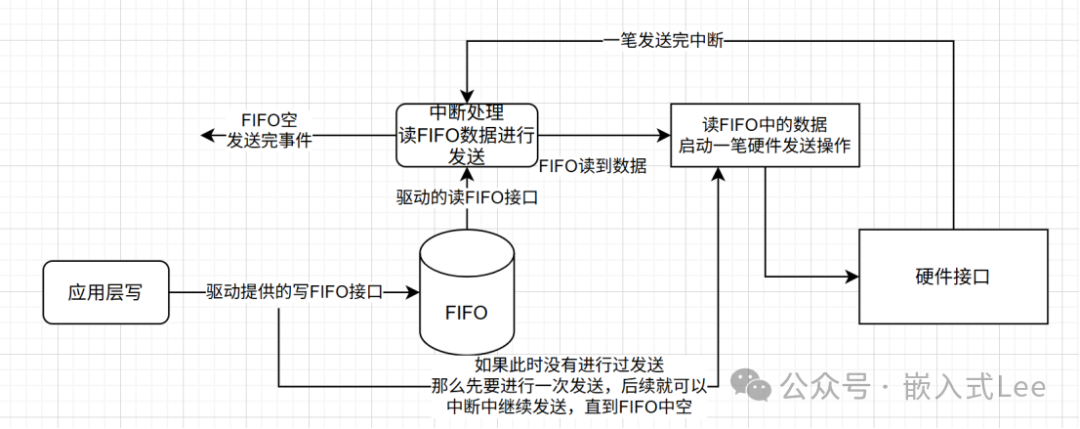
1)The application layer only needs to write data into the FIFO.
2)When the application layer sends data, if hardware sending has not been started before, it needs to start hardware sending first.
3)After one hardware sending is completed, the interrupt callback reads from the FIFO to continue subsequent sending. If the application layer writes quickly, there will always be data in the FIFO, allowing continuous streaming sending. Conversely, if there is no data in the FIFO, sending will stop.
4)If the hardware sending interface supports hardware FIFO, such as HALF interrupts, supports linked list DMA, or PING-PONG, then seamless streaming sending can be achieved. Otherwise, there will still be an interrupt handling time interval between each hardware sending.
5)The downside is that the application layer may not know when a write is completed unless it writes very slowly. The status can be known through the FIFO empty send complete event.
For block data, such as USB and Ethernet, each read/write is generally a block of data, so using a linked list approach is more suitable, where each node in the linked list represents a request and can associate request callback information.
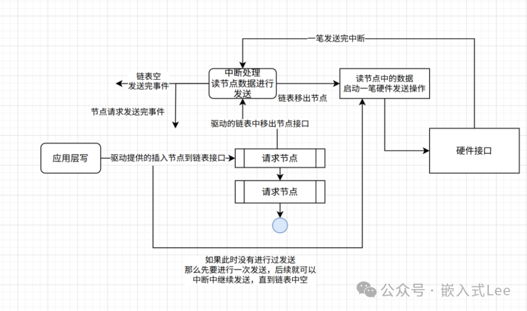
1)The application layer only needs to allocate a node, fill in the information, and add the node to the linked list.
2)When the application layer sends data, if hardware sending has not been started before, it needs to start hardware sending first.
3)After one hardware sending is completed, the interrupt callback reads the linked list to continue subsequent sending. If the application layer writes quickly, there will always be data in the linked list, allowing continuous streaming sending. Conversely, if there is no data in the linked list, sending will stop.
4)After each request is processed, the application can be notified through the callback in the node information, allowing the application to handle resource release.
5)If the hardware sending interface supports hardware FIFO, such as HALF interrupts, supports linked list DMA, or PING-PONG, then seamless streaming sending can be achieved. Otherwise, there will still be an interrupt handling time interval between each hardware sending.
6) The advantage is that each write from the application layer can have a corresponding event callback.
7) Priority management can be performed, creating different priority queues, and retransmission management can be done. When a node is taken out for sending, it can be added to the pending send linked list for retransmission processing.
3. Precautions and Bug Sharing
Both of the above modes have a critical point that, if not handled properly, can easily lead to errors. From the block diagram, it can be seen that there are two situations where a hardware sending operation is called, which may correspond to DMA configuration or related register configuration. One is done in the interrupt callback, and the other is done in the application layer interface, so the application layer interface needs to ensure proper critical section protection.
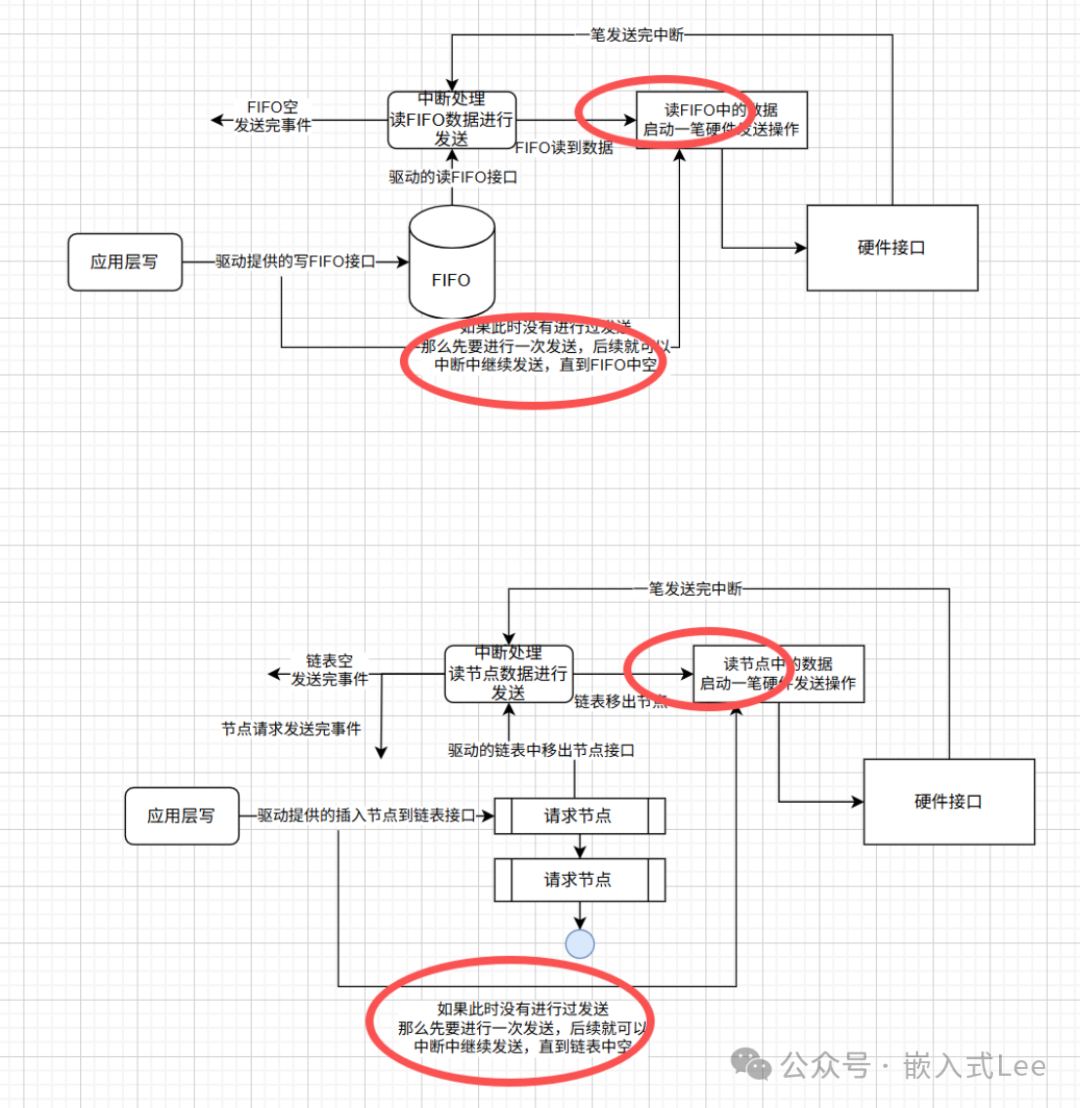
Additionally, how the application layer interface determines that the current hardware is not sending is also crucial, as the application layer interface can only actively call a send operation when the hardware is not currently sending. Otherwise, if the hardware is sending and the application layer actively calls a send operation, it will disrupt the ongoing hardware processing.
Here, I will share a bug from the DWC2 USB driver, which implements the aforementioned linked list approach.
In this implementation, when the application sends data, if it determines that the previous linked list is empty, it assumes that the current hardware is not sending. At this point, it will reconfigure a hardware sending operation, which involves configuring DMA related registers. However, an empty linked list does not necessarily mean that the hardware is not sending; it may be that the previous hardware DMA is still waiting to be processed, which could lead to overwriting the previous unprocessed DMA, causing exceptions.
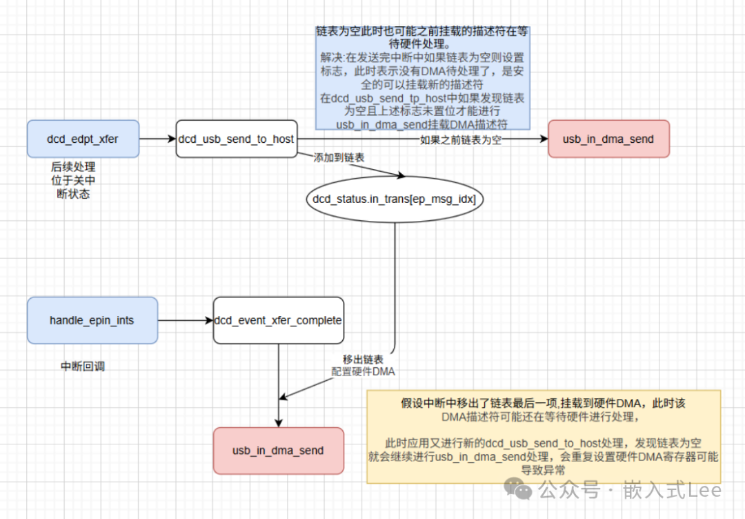
Solution: Since there is no suitable state to determine whether the hardware is processing a DMA, a flag is added to record this. When a DMA interrupt occurs and the current linked list is empty, the flag indicates that no DMA is being processed. The next time the application layer sends data, it can only actively perform a DMA sending operation when the linked list is empty and the flag is set.
4. Conclusion
This article shared a common driver design pattern, focusing on the precautions mentioned above and the shared bug case.