Click the “Mushroom Cloud Creation” above to follow us!
1. Overview
Hello World is the first lesson in learning any programming language, but in Arduino learning, our Hello World is called Blink. What does Blink mean? It means to flash. In fact, Blink is a program that lights up the onboard LED on the Arduino board and makes it blink.

Blink
2. Project Implementation
(1) Lighting the Onboard LED
Hardware Preparation:
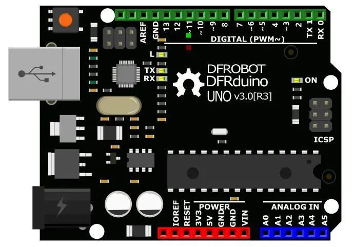
Main Control: Arduino UNO
Connection Cable: Type A to B USB cable
Software Preparation:
This tutorial uses Windows 10 as the operating system, Python version 3.8.5, and the built-in IDLE editor for Python. The Arduino board is driven using the Pinpong library.
1. Open the official Pinpong documentation, find the example program blink, and copy the code into IDLE.
2. For the blink.py example program, right-click and select Edit with IDLE → Edit with IDLE 3.8.5 to open the Python program for editing.
Programming:
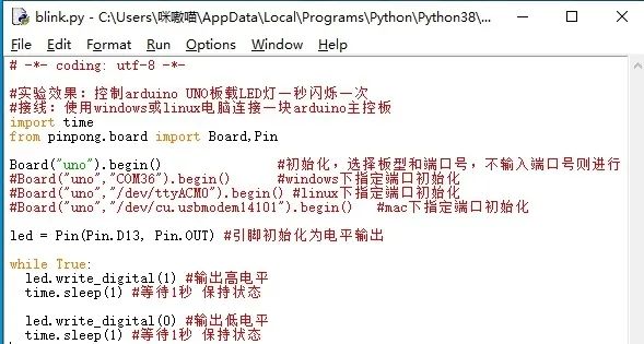
After connecting the Arduino Uno board to the computer via USB, there is no need to select a port; the port will be automatically recognized when running the program. If recognition fails, you can manually specify the COM port using the “Specify Port Initialization” method.
Note: The first time you use the Pinpong library, it will automatically upload the Firmata firmware to the Arduino board. Therefore, there is no need to upload firmware separately to the Arduino.
Press F5 to run the program, and it will prompt you to save the program. Click OK to save. If successful, a new window will pop up, and when the program runs as shown in the figure, it indicates success.
Check the effect. The onboard LED on the Arduino Uno will blink according to the pattern of being on for 1 second and off for 1 second. (If this step is not successful, you can check the FAQ in the official documentation.)
Note: Do not unplug the USB cable connected to the Arduino during program execution, and do not close the newly popped-up running window. If you unplug the cable or close the running window, the program functionality will stop executing.

Running Effect
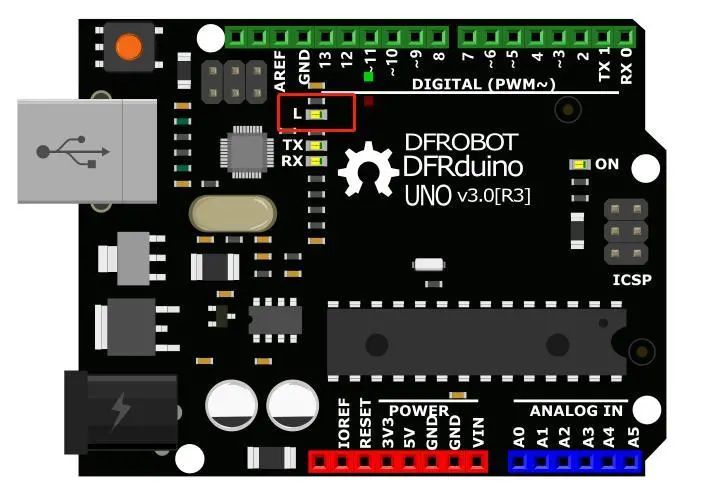
The LED in the red circle will blink according to the pattern of being on for 1 second and off for 1 second.
1. If we want to modify the blinking frequency of the small light, how should we modify the program? We just need to modify the duration of the delay in the code. For example, the modified effect is that the small light is on for 2 seconds and off for 1 second.
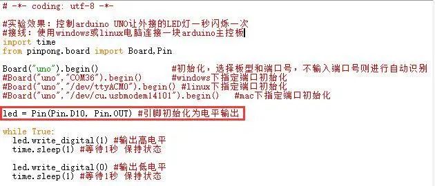
# -*- coding: utf-8 -*-
# Experimental effect: Control the Arduino UNO onboard LED to blink once every second
# Wiring: Connect an Arduino main control board to a Windows or Linux computer
import time
from pinpong.board import Board, Pin
Board(“uno”).begin() # Initialize, select board type and port number, if the port number is not entered, automatic recognition will occur
#Board(“uno”,”COM36″).begin() # Specify port initialization under Windows
#Board(“uno”,”/dev/ttyACM0″).begin() # Specify port initialization under Linux
#Board(“uno”,”/dev/cu.usbmodem14101″).begin() # Specify port initialization under Mac
led = Pin(Pin.D13, Pin.OUT) # Initialize the pin as output
while True:
led.write_digital(1) # Output high level
time.sleep(2) # Wait for 2 seconds to maintain the state
led.write_digital(0) # Output low level
time.sleep(1) # Wait for 1 second to maintain the state
(2) Lighting the External LED
Hardware Preparation:
Main Control: Arduino UNO, IO Sensor Expansion Board V7.1
Module: LED Light Module
Hardware Connection Diagram:
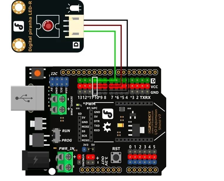
* Connect the expansion board to the Arduino Uno main control board, and be careful to align it when assembling to avoid bending the pins.
* Connect the LED module to digital pin 10.
Programming:
1. When wiring, we connected the external LED to pin 10, so we need to modify the program to light up this external small light by changing the led corresponding pin to 10.
2. If we want the small light to have a breathing light effect, how should we execute it? Find the PWM simulation output function in the example program and run it with Python IDLE.
3. Modify the pin number and port number, then run the program, and the small light will cycle through the commands to gradually brighten and extinguish.
Example Program
# -*- coding: utf-8 -*-
# Experimental effect: The small light will cycle through commands to gradually brighten and extinguish
# Wiring: Connect an Arduino main control board to a Windows or Linux computer, with the main control board D6 connected to an LED light module
import time
from pinpong.board import Board, Pin, PWM # Import PWM class to achieve simulation output
Board(“uno”).begin() # Initialize, select board type and port number, if the port number is not entered, automatic recognition will occur
#Board(“uno”,”COM36″).begin() # Specify port initialization under Windows
#Board(“uno”,”/dev/ttyACM0″).begin() # Specify port initialization under Linux
#Board(“uno”,”/dev/cu.usbmodem14101″).begin() # Specify port initialization under Mac
pwm0 = PWM(Pin(Pin.D6)) # Pass the Pin into PWM to achieve simulation output
while True:
for i in range(255): # Loop from 0 to 255
pwm0.duty(i) # Set the simulation output value
print(i)
time.sleep(0.05)
3. Code Analysis
Digital Signals and Analog Signals
Do you know what digital signals and analog signals are? Let’s first look at the concepts of digital signals and analog signals.
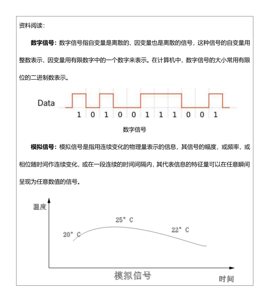
Just looking at the concepts feels particularly abstract, so let’s use real-life examples to understand. For example, the switch we usually use to turn on and off the light has two states: on and off. For the light, on and off are digital signals (low level and high level). Think about it: if there is a thermometer in your home, the temperature change is a continuously varying value and cannot be represented by any specific state; the change in temperature is an analog signal.
After understanding digital signals and analog signals, think about it: in this project, is the signal controlling the LED light on and off a digital signal or an analog signal?
4. Hardware Analysis
I wonder if you have noticed that in the second breathing light case, the LED light is connected to digital pin 10, but according to the concepts of digital signals and analog signals, it should be an analog signal to achieve the breathing light effect. Here we need to understand a new knowledge point: PWM signal.
Observe the digital pins on the Arduino UNO main control board in your hand; do some pin numbers have a * mark (some boards have a wave ~ mark)? These pins are the ones that support PWM signal output.
PWM (Pulse Width Modulation) is a method of analog control. In Arduino, PWM continuously switches between high and low levels to simulate an output that approximates an analog value. However, this only achieves an approximate analog output effect; to output a true analog value, it still needs to be executed on the analog pins.
