Click the “Mushroom Cloud Creation” above to follow us!
Let’s get started!
Let’s start our Arduino journey with an LED! You will learn how to control various outputs of Arduino just like controlling button inputs. On the hardware side, you will learn about LEDs, buttons, and resistors, including pull-up and pull-down resistor knowledge, which is very important for future projects. During this process, you will be exposed to Mind+ graphical programming; programming is not as difficult as you might think. By comparing the C code generated automatically by graphical programming, you can learn basic coding knowledge. Let’s begin with a very basic project, using Arduino to control an external LED blinking.
In the first project, we will reuse the previous Blink test code. The difference is that we need to connect an external LED to a digital pin instead of using the built-in LED 13 (the “L” light) on the development board. This will help us clearly understand how the LED works and how to build some hardware circuits.
Required Components
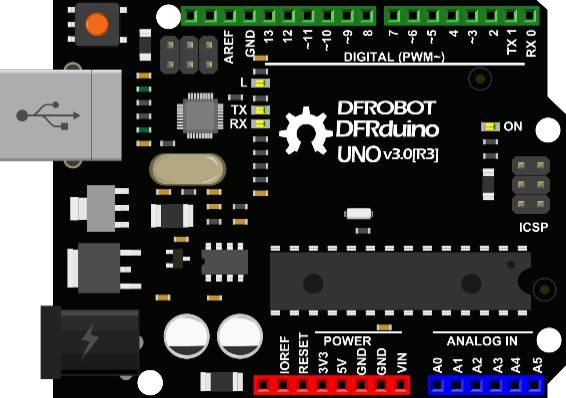
■ 1× DFduino UNO R3 (and a matching USB data cable)
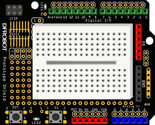
■ 1× Prototype Shield + Breadboard

* The resistor here is only a schematic; refer to the packaging for specific values. The value may vary depending on the LED you are using; later we will explain how to calculate this value.
Hardware Connection
First, take out the Prototype shield and breadboard from our kit, remove the double-sided tape from the back of the breadboard, and stick it onto the Prototype shield. Then take out the UNO and plug the breadboard with the Prototype shield into the UNO. Take out the required components and connect them according to the diagram LED Blinking 1-1.
* When connecting, note that there may be some version differences between the expansion board in the picture and the one in your hand. Make sure to refer to the labels under the used interfaces, rather than relying on the relative positions of the interfaces.
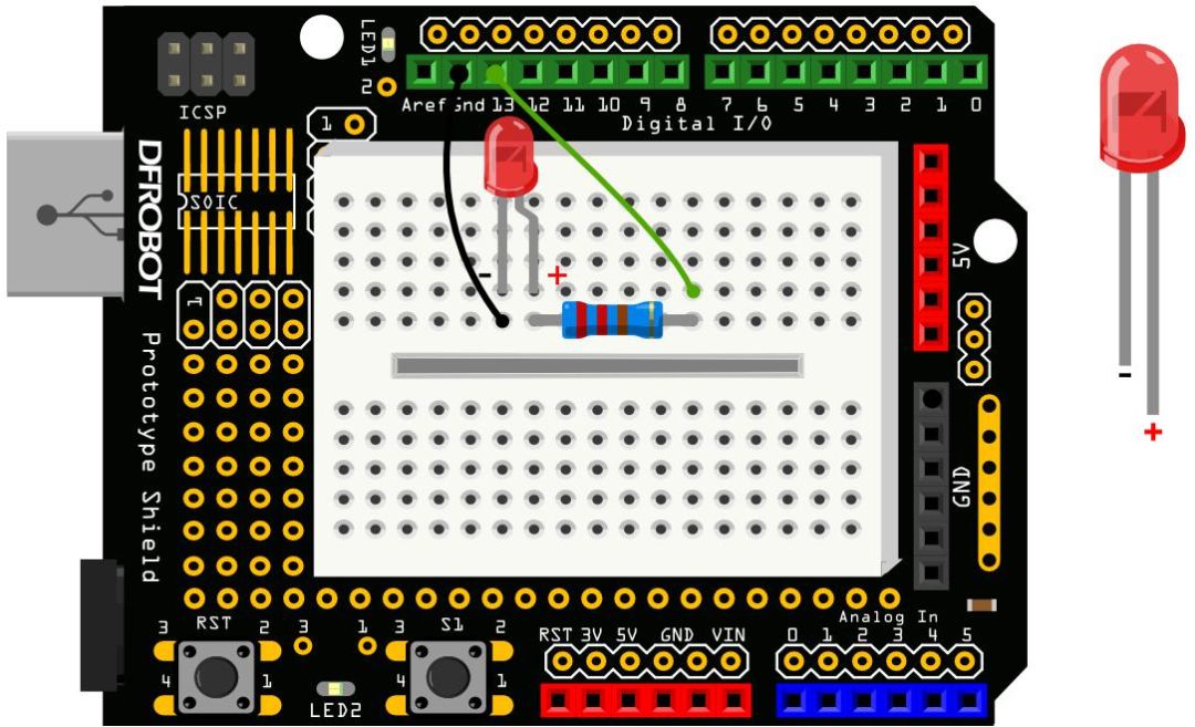
Diagram LED Blinking 1-1
Connect the components using green and black jumper wires (In DFRobot’s products, the definitions are as follows: green for digital ports, blue for analog ports, red for power VCC, black for GND, and white can be mixed and matched). It is also okay to use other holes on the breadboard, as long as the connection order of the components and wires remains consistent with the above diagram.
Ensure that the LED is connected correctly; the long leg of the LED is + (VCC), and the short leg is – (GND). After completing the connection, connect the Arduino to the USB data cable for power and prepare to download the program.
Graphical Programming
Open Mind+, complete the loading of the Arduino UNO library learned in the previous lesson, and connect the main board to the computer with a USB cable. Then select the main board in the device connection checkbox and connect. After that, drag the commands from the left command area to the script area. Input the sample program shown in Program Sample 1-1.
Sample Program 1-1:
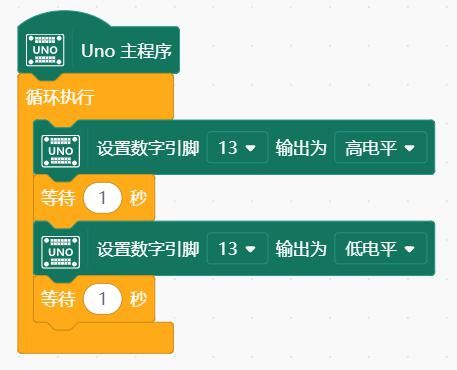
After entering, click ⬆ Upload to Device to download the program to Arduino.
Running Result: If all the above steps are completed, you should see the red LED on the breadboard blinking once every second.
Now let’s learn about the commands used in the program and see how they work.
Learning Graphical Commands
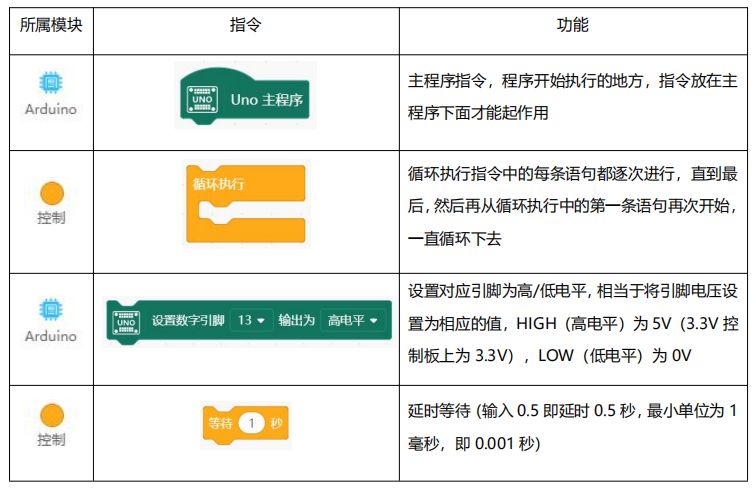
Through graphical programming, we have completed the LED blinking effect. Based on the C code automatically generated in the code area, let’s learn about the coding language together.
Code Learning
The C code for this project is as follows. Next, we will learn the meaning of each line of code:
1. void setup () {
2. }
3.
4. void loop() {
5. digitalWrite (13, HIGH);
6. delay (1000);
7. digitalWrite (13, LOW);
8. delay (1000);
9. }
■ void setup() {}

The part inside the braces of the function will be executed sequentially, starting from ” { ” and ending with ” } “. The statements between these two symbols belong to this function. The function inside the braces usually serves an initialization purpose, and the setup function runs only once when the Arduino is powered on or reset.
Function
Functions are usually small modules with specific functionalities. By integrating these functionalities, they form our entire code, achieving a complete functionality. These functional blocks can also be reused. This is where the benefits of functions come into play. During program execution, some functionalities may be reused, so you only need to call the function name in the program without rewriting it. The setup() and loop() functions are special and cannot be called repeatedly.
Another concept we need to understand is the return value of a function, which we can think of as feedback. How is the presence or absence of a return value reflected in a function? It is reflected in the function declaration, for example, ” void ” is the signal that the function has no return value, which we will often use later. We will not explain functions with return values for now; those interested can look it up online.
However, the setup and loop functions are special and can only be used once in a code.
Have you got a simple concept of functions? No worries if you don’t understand it; we will cover it in later projects.
■ void loop() {}

* Arduino programs must include both setup() and loop() functions; otherwise, they will not work properly.
The loop() function, as the name suggests, continuously loops during program execution. Each statement in the loop() function is executed sequentially until the last statement of the function, and then it starts again from the first statement of the loop function, repeating this process until the Arduino is turned off or the reset button is pressed.
■ digitalWrite(13, HIGH)

■ delay(1000)

The delay() function corresponds to the command wait1second for delaying. Note that the time unit of the delay function is milliseconds; 1000 milliseconds equals 1 second. By analogy, if we need to delay for 0.5 seconds, what is the corresponding code? The answer is: delay(500).
■ digitalWrite(13, LOW)
With the guidance above, is this statement easy to understand? It means to give pin 13 a 0V low level, which turns off the LED.
Extension Practice
Now that we know how the code works, let’s make a small modification! Keep the LED off for 5 seconds, then blink quickly (0.25 seconds), just like the LED indicator on a car alarm. Try to write it!
Answer:
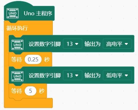
By changing the time the LED is on and off, different effects can be produced. Rapid alternation creates a dynamic feeling, while slower alternation feels softer. Many external lighting effects are based on this principle.
Hardware Review
Prototype Shield
The port resources on the Arduino UNO are very precious. Especially the power supply interfaces, such as 5V and GND, are only 2 to 3 on the board. Therefore, when setting up multiple devices, if you need multiple GND or 5V interfaces, you will run out of port resources. Thus, a port expansion board is necessary to fully expand Arduino’s resources.
The Prototype Shield, used in conjunction with Arduino UNO, is for building circuit prototypes. Components can be soldered directly onto the board or connected through the mini breadboard above. The breadboard is attached to the circuit board with double-sided tape. Take a look at this board; the digital and analog ports correspond one-to-one with the UNO. Additionally, the 5V marked in the diagram below are all interconnected, and the same goes for GND; they are all interconnected. (The wiring diagrams for subsequent projects will use the old version as an example).
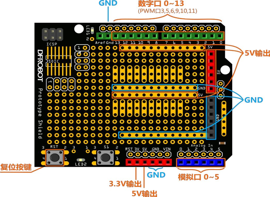
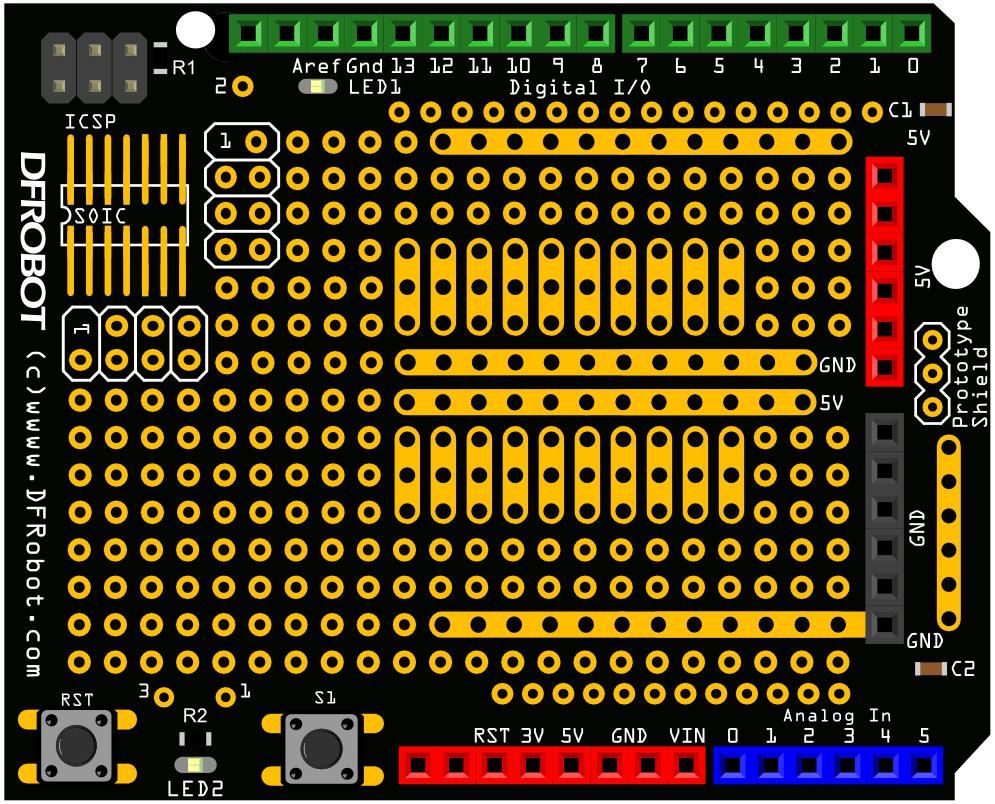
(New version of the Prototype Shield)
Breadboard
A breadboard is a reusable, non-soldering component used to create electronic circuit prototypes or designs. In simple terms, a breadboard is an electronic experiment component; the surface is made of perforated plastic, and the bottom has metal strips, allowing for conduction without soldering. How to use a breadboard? It’s quite simple: just insert electronic components and jumper wires into the holes on the board; how to insert them will be explained based on the internal structure of the breadboard.
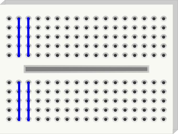
From the above image, we can see that the breadboard is divided into two parts, with the blue lines indicating that every 5 holes in the vertical direction are interconnected. Some might ask why the two parts are not fully connected? The groove in the middle of the breadboard is designed for a reason. The hole spacing between the two sides of the groove is exactly 7.62mm, which is just enough to insert standard narrow-body DIP pin ICs.
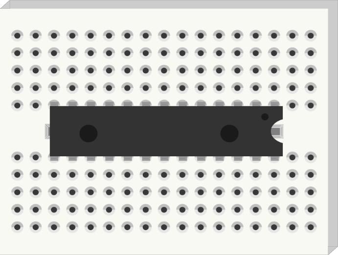
Once the IC is inserted, it’s generally difficult to remove it due to the many pins, and forcing it can easily bend the pins. This groove allows you to use tweezers or similar tools to slowly remove the IC.
Resistor
The next component to discuss is the resistor. The unit of resistance is Ω. Resistors create a certain resistance to current, causing a voltage drop across them. You can think of a resistor as a water pipe that is slightly narrower than the pipes connected to it. When water (current) flows into the resistor, due to the narrowing, the water flow (current) coming out of the other end is reduced. The same principle applies to resistors, so resistors can be used to reduce the current or voltage for other components.
Resistors have many uses and different names, such as pull-up resistors, pull-down resistors, current-limiting resistors, etc. Here, we use it as a current-limiting resistor. In this example, the digital pin 10 outputs a voltage of 5V with an input current of 40mA (milliamps) of direct current. A standard LED requires about 2V of voltage and around 35mA of current. Therefore, to light the LED at its maximum brightness, a resistor is needed to reduce the voltage from 5V to 2V and the current from 40mA to 35mA. This resistor serves as a current limiter.
If no resistor is connected, the current flowing through the LED will be too high (you can think of it as water flowing too fast, causing the pipe to burst!), which will burn out the LED, and you will see a wisp of smoke accompanied by a burnt smell~
We won’t go into the calculations for selecting the resistor value; just know that when connecting an LED, a resistor of about 100Ω is needed. A larger value is also okay, but it cannot be less than 100Ω. If the selected resistor value is too high, the LED will not be significantly affected, but it will appear dimmer. This is easy to understand; the larger the resistor, the more obvious the effect of current or voltage reduction. The LED dims as the current decreases.
Reading Resistor Color Codes
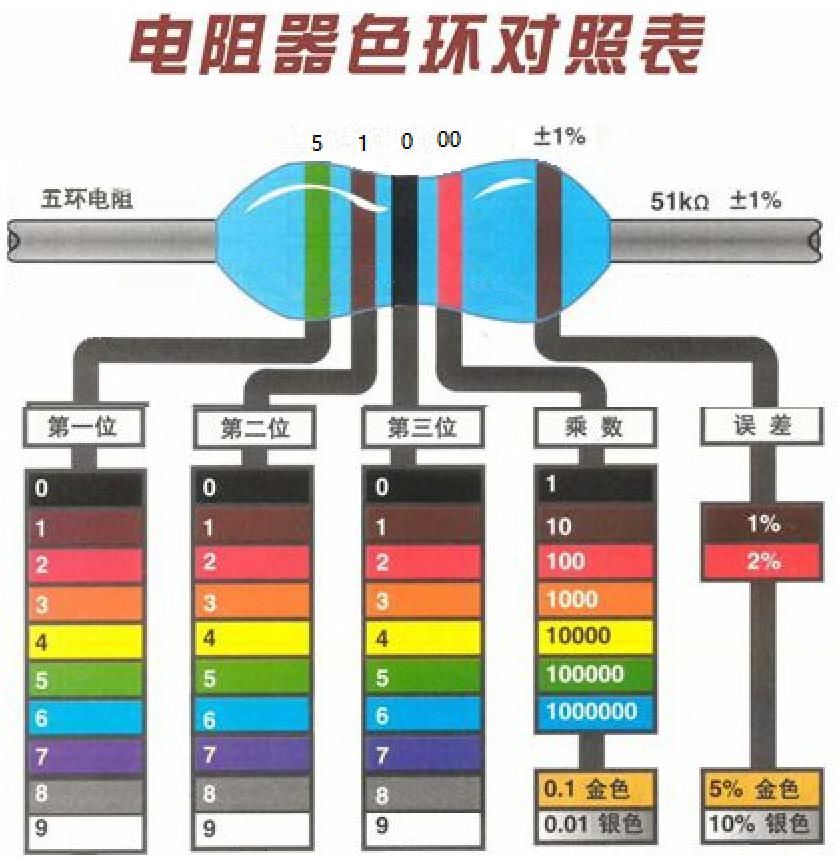
The packaging of our components clearly indicates the names of each component. However, there may be times when the label accidentally falls off, and you don’t have a measuring tool at hand; what should you do? One method is to read the resistance value from the color bands on the resistor. We won’t go into detail here; interested students can refer to the diagram below to read the values.
LED
Finally, let’s discuss the LED, the standard light-emitting diode, which is a type of diode. A diode is an electronic device that allows current to flow in only one direction. It acts like a valve in a water flow system, allowing flow in only one direction. If the current attempts to change direction, the diode will prevent it from doing so. Therefore, the role of a diode in a circuit is usually to prevent accidental connections between the power supply and ground, avoiding damage to other components.
LEDs are also diodes that emit light. LEDs can emit different colors and brightness levels, including ultraviolet and infrared light in the spectrum. (For example, the various LEDs used in remote controls are one type of LED, similar in appearance to ordinary light-emitting diodes, but the light they emit is invisible to the human eye; we also refer to them as infrared emitters.)
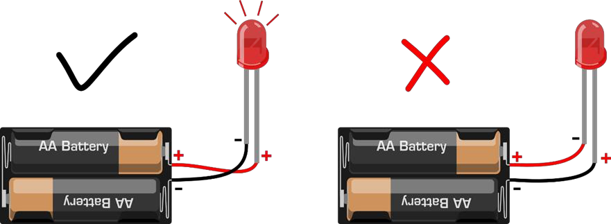
If you observe an LED closely, you will notice that the LED leads are of different lengths; the longer lead is +, and the shorter lead is -. What happens if you connect them in reverse? The image below illustrates the issue; if connected in reverse, it won’t light up. Is there something missing in the diagram? Did you notice the lack of a resistor?
In our kit, there is also a type of LED with four leads; don’t think we’ve made a mistake. This LED has great functionality; it can display different colors and is called an RGB LED. We know that red, green, and blue are the three primary colors. By combining these three colors’ brightness changes, any color you desire can be produced. By placing these three colors in the same casing, you can achieve this effect. We will introduce this in future projects.
Now that you understand the functions of each component and how the entire project works in terms of software and hardware, let’s try to create other fun things!
——————— End of Text ———————
The purpose of education is to cultivate students’ collaboration skills, communication skills, critical thinking, and creativity, with creativity being the core. As one of the few one-stop maker education service providers in China, Mushroom Cloud Maker Education aims to cultivate children’s creativity.
To better connect the knowledge students learn in class with the real world, Mushroom Cloud will guide schools in planning, establishing, and operating their maker spaces. Additionally, they have differentiated designs and layouts based on different student age groups.
Elementary school maker spaces focus on fun,
emphasizing interactive scenarios;
Middle school maker spaces focus on practicality,
emphasizing learning scenarios;
High school maker spaces focus on technology,
emphasizing application scenarios;
In terms of content, Mushroom Cloud collaborates with leading maker teachers in China to compile a series of textbooks suitable for domestic maker education. They also have a complete maker education curriculum system, including course content and teaching tools, course training, and technical Q&A. Similarly, the course classification and design will differ based on different student age groups.
Elementary school students learn through gamification and experiential methods, focusing on “learning through play”.
Middle school students are guided to engage in inquiry-based learning through hands-on activities, promoting “learning through doing”.
High school students engage in problem-based and design-based learning, requiring teachers to create relevant real-world scenarios for students to “learn through thinking”.
Recommended Reading:
[Introduction to Arduino & Mind+] Getting Started with Mind+ Arduino Tutorial 00
[Teaching Activity Case] Designing a Smart Home Model — Taking the Access Control System as an Example
Mind+: Inclusive and born for maker education!
Virtual Valley Quick Start (V1.0)
Formaldehyde Detection in New and Old Cars — Based on IoT Scientific Inquiry Activity Case
[Virtual Valley IoT and Scientific Inquiry] The Diffusion Process of Salt in Water “Visible”
What should we learn in the era of artificial intelligence?
What are the differences between micro:bit, Arduino, and control boards?
First Lesson of the Semester, Coding as a Highlight!
I know you are watching!
