[STM32F103C8T6 Tutorial] ① Install Keil5 and STM32 Support Packagehttps://mbb.eet-china.com/forum/topic/147436_1_1.html

Keil5, full name Keil μVision 5, is a powerful integrated development environment (IDE) launched by Keil (now part of Arm) specifically for software development of embedded systems. Keil5 includes three versions: MDK, DS-MDK, and MDK-Lite, among which MDK is the most comprehensive version, supporting the most devices and functions. It provides a complete development environment, including editor, compiler, debugger, etc., and supports multiple processor architectures such as ARM, Cortex-M, Cortex-A, Cortex-R, and 8051.Wide device support: Keil5 supports a wide range of embedded devices, including but not limited to microcontrollers based on ARM, Cortex-M, Cortex-R, and 8051 architectures. Comprehensive development environment: Provides source code editor, project manager, debugger, and tools, as well as features like simulator, advanced debugging tools, cloud development support, and real-time operating system support. User-friendly interface: Keil5 has a user-friendly interface, supports multiple programming languages such as C, C++, and assembly language, and provides rich technical support and documentation. Device database: Contains a large amount of data and configuration information for microcontrollers (MCUs), helping developers quickly set up and configure the development environment for specific microcontrollers. Powerful debugging capabilities: Allows developers to run programs and set breakpoints in the code, step through the program, check variable values, and call stacks to identify errors and issues.[STM32F103C8T6 Tutorial]
② Introduction to STM32F103C8T6, LED Blinking Test(1) Introduction We can first familiarize ourselves with the programming software for STM32F103C8T6, Keil5. Since configuring the environment can be quite troublesome, it is recommended to use a project template.
It is usually convenient to add some functions or develop based on the project template. (2) Project Template
 Project Template: https://wwmg.lanzouj.com/i9Fx72h0jq9e①DebugConfig, Listings, Objects are automatically generated when creating a project, used to store debugging files②User, Start, Library folders are created by the user to store application programs and standard library files③Project.uvprojx is the project file, click this to directly open the project (for how the template came about and what the configuration files are for, this tutorial will not go into detail, detailed information is explained in the video from Jiangsu University) (3) Configuring GPIO Lighting up is actually configuring the GPIO pin’s high and low levels, so we need to understand the GPIO configuration process ① Enable GPIO Clock In the clock library function STM32f10x_rcc.h, you can find void RCC_APB2PeriphClockCmd(uint32_t RCC_APB2Periph, FunctionalState NewState); So according to the position of the onboard LED, port C13, we can get the following function
RCC_APB2PeriphClockCmd(RCC_APB2Periph_GPIOC, ENABLE); // Enable GPIOC clock
② Configure GPIO Parameters In the GPIO configuration library stm32f10x_gpio.h, you can find GPIO_InitStructure.GPIO_Mode pin working mode GPIO_InitStructure.GPIO_Pin GPIO pin GPIO_InitStructure.GPIO_Speed pin speed GPIO_InitTypeDef GPIO_InitStructure; Define a structure variable GPIO_Init(GPIOC, &GPIO_InitStructure); Pass the configured structure variable to the GPIO_Init function. We know that the LED on the board is on pin C13 and is in output mode, speed is set to 50MHz.
GPIO_InitTypeDef GPIO_InitStructure; GPIO_InitStructure.GPIO_Mode = GPIO_Mode_Out_PP; GPIO_InitStructure.GPIO_Pin = GPIO_Pin_13; GPIO_InitStructure.GPIO_Speed = GPIO_Speed_50MHz; GPIO_Init(GPIOC, &GPIO_InitStructure);
In the system, we can see the already written delay function. Delay is a very important function; let’s see how STM32 implements it.
void Delay_us(uint32_t xus){ SysTick->LOAD = 72 * xus; // Set the timer reload value SysTick->VAL = 0x00; // Clear the current count value SysTick->CTRL = 0x00000005; // Set clock source to HCLK, start timer while(!(SysTick->CTRL & 0x00010000)); // Wait for count to 0 SysTick->CTRL = 0x00000004; // Stop timer}
1. void Delay_us(uint32_t xus) This is a function definition, the function name is Delay_us, it takes a 32-bit unsigned integer parameter xus, which represents the number of microseconds to delay. 2. SysTick->LOAD = 72 * xus; This line of code sets the reload value of the SysTick timer. Since the STM32’s SysTick timer counts down, it generates a SysTick interrupt when it counts to 0 (if the interrupt is enabled). Here, 72 usually indicates that the system clock frequency (HCLK) of STM32 is 72MHz, which means 72,000,000 clock cycles per second. Therefore, 72 * xus calculates the number of clock cycles needed to achieve xus microseconds and sets it as the reload value. Note that this calculation assumes the system clock frequency is 72MHz; in practical applications, this value needs to be adjusted according to the specific system clock frequency. 3. SysTick->VAL = 0x00; This line of code clears the current value of the SysTick timer (VAL register), starting the count from the maximum value (the value of the LOAD register). 4. SysTick->CTRL = 0x00000005; This line of code configures the control register of the SysTick timer (CTRL register). The value 0x00000005 does the following: – Bit 0 (ENABLE bit) is set to 1, starting the SysTick timer.– Bit 2 (CLKSOURCE bit) is set to 1, selecting HCLK (system clock) as the clock source for the SysTick timer.– Bit 16 (TICKINT bit) remains 0, indicating that the SysTick interrupt is not enabled. 5. while(!(SysTick->CTRL & 0x00010000)); This line of code is a busy-wait loop that checks the 17th bit (COUNTFLAG bit) of the CTRL register. When the SysTick counter counts down to 0, the COUNTFLAG bit will be set to 1 by hardware. Thus, this loop will keep executing until the SysTick counter reaches 0, indicating that the delay is complete. 6. SysTick->CTRL = 0x00000004; Finally, this line of code stops the SysTick timer by clearing the ENABLE bit (setting the CTRL register value to 0x00000004). This is to prevent the timer from continuing to run after the function returns, which may interfere with other functions that use the SysTick timer.It doesn’t matter if you don’t understand the above analysis; just using the delay function is enough.
Delay_ms(500);// Delay 500ms
Delay_us(500);// Delay 500us
Delay_s(5);// Delay 5s
(5) LED Blinking After configuring GPIO and the delay function, we can make an LED blink.
Our program is written in the main.c function inside User, first including the STM32 library, and the delay library.
#include "stm32f10x.h"    // Device header
#include "Delay.h"
RCC_APB2PeriphClockCmd(RCC_APB2Periph_GPIOC, ENABLE);
  GPIO_InitTypeDef GPIO_InitStructure;                // Define structure variable  GPIO_InitStructure.GPIO_Mode = GPIO_Mode_Out_PP;  GPIO_InitStructure.GPIO_Pin = GPIO_Pin_13;  GPIO_InitStructure.GPIO_Speed = GPIO_Speed_50MHz;  GPIO_Init(GPIOC, &GPIO_InitStructure);
You can use GPIO_ResetBits (low level), GPIO_SetBits (high level) to control the pin. And add the delay function Delay_ms(500); to achieve the blinking effect.
GPIO_ResetBits(GPIOC, GPIO_Pin_13);  // Set PC13 pin to low level
Delay_ms(500);                       // Delay 500ms
GPIO_SetBits(GPIOC, GPIO_Pin_13);    // Set PC13 pin to high level
Delay_ms(500);                       // Delay 500ms
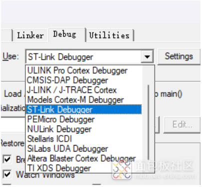
(6) Programming The programming tool I am using is ST link v2.
In the debug options, you can select our downloader, here select ST link.
Click Settings, and see the board information read on the right, which indicates a successful connection.
We also need to select the board’s Flash in Flash Download, here choose 128k, and then click Add.
In the upper left corner, click the third one to compile everything.
0 errors 0 warnings, indicating that the program is fine.
Click the green download button to download the program to the board.
(7) Program PhenomenonYou can see that the onboard LED blinks at an interval of 500ms.
Free application for development board

Submission/Promotion/Cooperation/Add Group Please scan the QR code to add WeChat
(Please note the purpose, when adding to the group please note city-name-industry position information)